Tx Polling
This example demonstrates the data transmission function using the I2S peripheral in polling mode.
Connect the I2S TX pin to the Logic Analyzer to observe the waveform of the transmitted data.
Requirements
For requirements, please refer to the Requirements.
Wiring
Connect P3_2, P3_3, and P4_0 on the EVB to a Logic Analyzer.
P3_2 is LRCK, P3_3 is BCLK, and P4_0 is DATA.
Building and Downloading
For building and downloading, please refer to the Building and Downloading.
Experimental Verification
After the EVB starts, observe the I2S output waveform using a Logic Analyzer. The I2S output waveform is shown in the following figure.
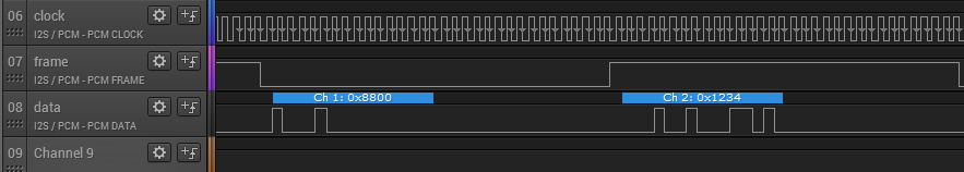
I2S output waveform
Code Overview
This section introduces the code and process description for initialization and corresponding function implementation in the sample.
Source Code Directory
The directory for project file and source code are as follows:
Project directory:
sdk\samples\peripheral\i2s\tx_polling\projSource code directory:
sdk\samples\peripheral\i2s\tx_polling\src
Initialization
The initialization flow for peripherals can refer to Initialization Flow in General Introduction.
-
Call
Pad_Config()andPinmux_Config()to configure the PAD and PINMUX of the corresponding pins.void board_i2s_init(void) { Pad_Config(I2S_BCLK_PIN, PAD_PINMUX_MODE, PAD_IS_PWRON, PAD_PULL_NONE, PAD_OUT_ENABLE, PAD_OUT_LOW); Pad_Config(I2S_LRCK_PIN, PAD_PINMUX_MODE, PAD_IS_PWRON, PAD_PULL_NONE, PAD_OUT_ENABLE, PAD_OUT_LOW); Pad_Config(I2S_DATA_TX_PIN, PAD_PINMUX_MODE, PAD_IS_PWRON, PAD_PULL_NONE, PAD_OUT_ENABLE, PAD_OUT_LOW); Pinmux_Config(I2S_BCLK_PIN, I2S_BCLK_PINMUX); Pinmux_Config(I2S_LRCK_PIN, I2S_LRCK_PINMUX); Pinmux_Config(I2S_DATA_TX_PIN, I2S_DATA_TX_PINMUX); }
Call
RCC_PeriphClockCmd()to enable the I2S clock.-
Initialize the I2S peripheral:
Define a
I2S_InitTypeDeftypeI2S_InitStruct, callI2S_StructInit()to pre-fillI2S_InitStructwith default values.Modify the parameters of
I2S_InitStructas required. The initialization parameter configuration for I2S is shown in the table below.Call
I2S_Init()to initialize the I2S peripheral.
I2S Hardware Parameters |
Setting in the |
I2S |
|---|---|---|
Clock Source |
||
Sample Rate (Mi) |
0x271 |
|
Sample Rate (Ni) |
0x10 |
|
Device Mode |
||
Channel Type |
||
Data Width |
||
Data Format |
-
Enable the I2S TX function.
I2S_Cmd(I2S_NUM, I2S_MODE_TX, ENABLE);
Functional Implementation
Define the data to be sent, and use I2S_SendData() to continuously send the data. The data sent by I2S can be observed in the Logic Analyzer.
void i2s_senddata(void)
{
    uint32_t i = 0x12348800;

    while (1)
    {
        if (I2S_GetTxFIFOFreeLen(I2S_NUM))
        {
            /* 16bit format, lower half word send first! */
            I2S_SendData(I2S_NUM, i++);
        }
    }
}
See Also
Please refer to the relevant API Reference: