Arbitrary Length Transmit and Receive - GDMA
This sample uses UART and GDMA to communicate data of arbitrary length with a PC terminal.
The SoC uses GDMA to receive data input from the PC terminal, transferring the data from the UART RX FIFO peripheral to Memory. Meanwhile, in the UART_FLAG_RX_IDLE interrupt, it retrieves the length of data of arbitrary length, processes the data, and sets the received_flag.
Once the received_flag is set, the SoC uses GDMA to transfer the received data from Memory to the UART TX FIFO peripheral, sending it back to the PC terminal.
In this sample, any length of data sent by the PC terminal will receive the same data information back from the SoC.
Users can change the pin configuration, GDMA configuration, and other information in the sample through different macro configurations. For specific macro configurations, see Configurations.
Requirements
For requirements, please refer to the Requirements.
In addition, it is necessary to install serial port assistant tools such as PuTTY or UartAssist on the PC terminal.
Configurations
-
The following macros can be configured to modify GDMA channel settings.
// Set the following macros to modify the UART TX GDMA Channel configurations.
#define UART_TX_GDMA_CHANNEL_NUM            GDMA_CH_NUM3
#define UART_TX_GDMA_CHANNEL                GDMA_Channel3
#define UART_TX_GDMA_CHANNEL_IRQN           GDMA_Channel3_IRQn
#define UART_TX_GDMA_Handler                GDMA_Channel3_Handler

// Set the following macros to modify the UART RX GDMA Channel configurations.
#define UART_RX_GDMA_CHANNEL_NUM            GDMA_CH_NUM4
#define UART_RX_GDMA_CHANNEL                GDMA_Channel4
#define UART_RX_GDMA_CHANNEL_IRQN           GDMA_Channel4_IRQn
#define UART_RX_GDMA_Handler                GDMA_Channel4_Handler
-
The following macros can be configured to modify the pin definitions.
#define UART_TX_PIN                         P3_0
#define UART_RX_PIN                         P3_1
-
The following macros can be configured to modify the Block Size of GDMA RX Channel.
#define GDMA_BLOCK_SIZE 5
Wiring
Connect P3_0(UART TX Pin) to the RX pin of the FT232 and P3_1(UART RX Pin) to the TX pin of the FT232.
Building and Downloading
For building and downloading, please refer to the Building and Downloading.
Experimental Verification
Preparation Phase
Start a PC terminal like PuTTY or UartAssist and connect to the used COM port with the following UART settings:
Baud rate: 115200
8 data bits
1 stop bit
No parity
No hardware flow control
Testing Phase
-
After resetting the EVB, observe the log information as shown in the Debug Analyzer.
Start uart tx rx unfixedlen by gdma test!
-
Type strings on the PC terminal and observe that the same string appears on the PC terminal. Simultaneously, observe that received data and interrupt information appear in the Debug Analyzer. Assuming the input data length on the PC terminal is number, the interrupt log for different cases is as follows:
GDMA0_Channel4_Handler  /* time = (number / block_size) > 0 triggers time interrupts and print logs. */

UART_FLAG_RX_IDLE       /* time = (number % block_size) > 0 and meeting the UART_FLAG_RX_IDLE interrupt condition triggers time interrupts and print logs. */
value is 0x..
value is 0x..
value is 0x..
...

UART_TX_GDMA_Handler    /* Once received_flag is set, the SoC uses GDMA to send number length data back to the PC terminal. Upon completion, it triggers the interrupt and prints logs. */
Code Overview
This section introduces the code and process description for initialization and corresponding function implementation in the sample.
Source Code Directory
The directory for project file and source code are as follows:
Project directory:
sdk\samples\peripheral\uart\unfixedlen_gdma\projSource code directory:
sdk\samples\peripheral\uart\unfixedlen_gdma\src
Initialization
The initialization flow for peripherals can refer to Initialization Flow in General Introduction.
-
Call
Pad_Config()andPinmux_Config()to configure the PAD and PINMUX of the corresponding pins. IfUART_CONFIG_HW_FLOW_CTRLis set to1, the CTS and RTS pins still need to be configured.void board_uart_init(void) { Pad_Config(UART_TX_PIN, PAD_PINMUX_MODE, PAD_IS_PWRON, PAD_PULL_UP, PAD_OUT_DISABLE, PAD_OUT_HIGH); Pad_Config(UART_RX_PIN, PAD_PINMUX_MODE, PAD_IS_PWRON, PAD_PULL_UP, PAD_OUT_DISABLE, PAD_OUT_HIGH); Pinmux_Config(UART_TX_PIN, UART3_TX); Pinmux_Config(UART_RX_PIN, UART3_RX); }
Call
RCC_PeriphClockCmd()to enable the UART clock.-
Initialize the UART peripheral:
Define the
UART_InitTypeDeftypeUART_InitStruct, and callUART_StructInit()to pre-fillUART_InitStructwith default values.Modify the
UART_InitStructparameters as needed. The UART initialization parameter configuration is shown in the table below.Call
UART_Init()to initialize the UART peripheral.
UART Hardware Parameters |
Setting in the |
UART |
|---|---|---|
UART Baudrate Parameter - div |
|
|
UART Baudrate Parameter - ovsr |
|
|
UART Baudrate Parameter - ovsr_adj |
|
|
GDMA Enable |
||
TX GDMA Enable |
||
RX GDMA Enable |
||
TX Waterlevel |
1 |
|
RX Waterlevel |
1 |
Configure UART receive idle interrupt
UART_INT_RX_IDLEand line status interruptUART_INT_LINE_STS, and configure NVIC. For NVIC related configuration, refer to Interrupt Configuration.-
Initialize the GDMA peripheral:
Define a
GDMA_InitTypeDeftypeGDMA_InitStruct, and callGDMA_StructInit()to pre-fillGDMA_InitStructwith default values.Modify the
GDMA_InitStructparameters as needed. The initialization parameters for the GDMA TX and RX channels are configured as shown in the table below. CallGDMA_Init()to initialize the GDMA peripheral.Configure the GDMA total transfer complete interrupt
GDMA_INT_Transferand NVIC. For NVIC configurations, refer to Interrupt Configuration.Call
GDMA_Cmd()to enable the corresponding GDMA channel transfer.
GDMA Hardware Parameters |
Setting in the |
GDMA TX Channel |
GDMA RX Channel |
|---|---|---|---|
Channel Num |
3 |
4 |
|
Transfer Direction |
|||
Buffer Size |
- |
|
|
Source Address Increment or Decrement |
|||
Destination Address Increment or Decrement |
|||
Source Data Size |
|||
Destination Data Size |
|||
Source Burst Transaction Length |
|||
Destination Burst Transaction Length |
|||
Source Address |
|
|
|
Destination Address |
|
|
|
Source Handshake |
- |
||
Destination Handshake |
- |
Functional Implementation
The flow for UART to send and receive data of arbitrary length via GDMA is shown in the diagram:
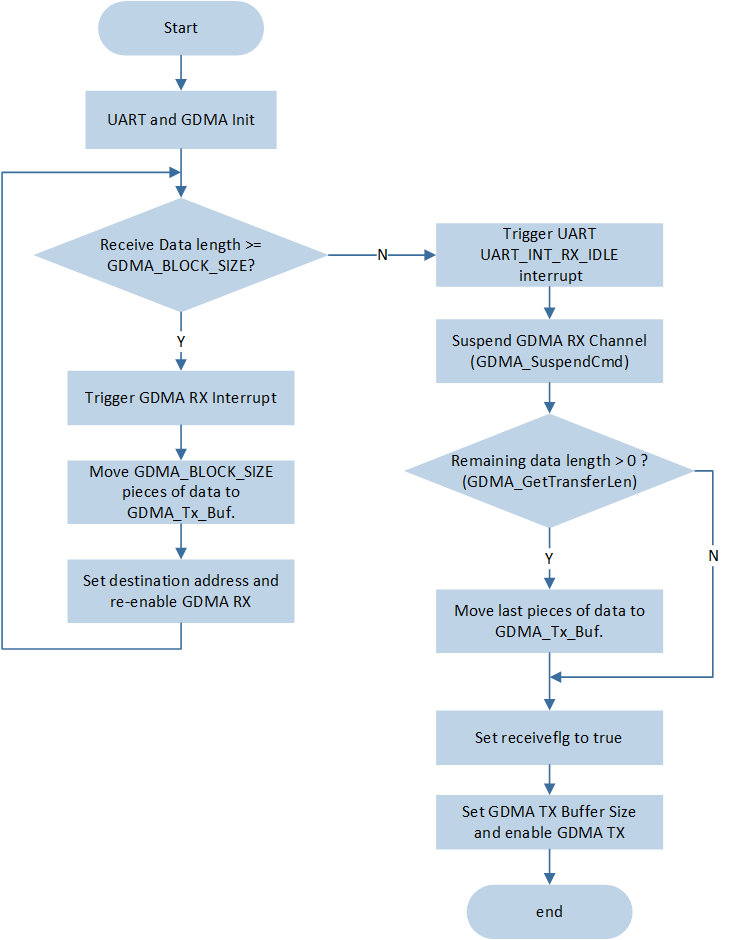
UART GDMA transmitting and receiving data of arbitrary Length flow
After enabling the GDMA RX channel transmission, when characters are input at the PC terminal, the GDMA RX channel moves the data from (&(UART_DEMO->UART_RBR_THR)) to GDMA_Rx_Buf.
Assuming the input data length on the PC terminal is number, the interrupt for different cases is as follows:
-
If number /
GDMA_BLOCK_SIZE> 0, meaning the length of data received by UART is greater thanGDMA_BLOCK_SIZE, a GDMA RX interrupt will be triggered every timeGDMA_BLOCK_SIZEamount of data is received, triggering a total of number / block_size times. The data received in the GDMA interrupt is saved toGDMA_Tx_Buf, and the GDMA RX channel is re-enabled for continued reception.void GDMA0_Channel4_Handler(void) { DBG_DIRECT("GDMA0_Channel4_Handler"); /* Clear interrupt */ GDMA_Cmd(UART_RX_GDMA_CHANNEL_NUM, DISABLE); GDMA_ClearAllTypeINT(UART_RX_GDMA_CHANNEL_NUM); receive_offset += GDMA_BLOCK_SIZE; count += 1; ... memcpy(GDMA_Tx_Buf + GDMA_BLOCK_SIZE * (count - 1), GDMA_Rx_Buf, GDMA_BLOCK_SIZE); GDMA_ClearINTPendingBit(UART_RX_GDMA_CHANNEL_NUM, GDMA_INT_Transfer); /* reset gdma param */ GDMA_SetDestinationAddress(UART_RX_GDMA_CHANNEL, (uint32_t)GDMA_Rx_Buf); GDMA_Cmd(UART_RX_GDMA_CHANNEL_NUM, ENABLE); }
-
If number /
GDMA_BLOCK_SIZE= 0, since the amount of data transferred is insufficient, no GDMA RX interrupt will be triggered. Once all data in the UART RX FIFO is moved, if no data is placed in the RX FIFO within the idle timeout period, theUART_INT_RX_IDLEinterrupt will be triggered.Pause the
UART_RX_GDMA_CHANNELchannel transmission and disable theUART_INT_RX_IDLEinterrupt.Obtain the data transfer amount for this GDMA and save the received data to
GDMA_Tx_Buf.Record the length of data received
receive_offsetand setreceiveflgtotrue, indicating data reception is complete.Reinitialize the GDMA RX channel, clear the UART FIFO, and re-enable the
UART_INT_RX_IDLEinterrupt for the next round of data transfer reception.
void UART3_Handler(void)
{
    ...
    if (UART_GetFlagState(UART3, UART_FLAG_RX_IDLE) == SET)
    {
        /*  Suspend GDMA_Channel2   */
        GDMA_SuspendCmd(UART_RX_GDMA_CHANNEL, ENABLE);
        UART_INTConfig(UART3, UART_INT_RX_IDLE, DISABLE);
        data_len = GDMA_GetTransferLen(UART_RX_GDMA_CHANNEL);
        ...

        if (data_len)
        {
            receive_offset += data_len;
            memcpy(GDMA_Tx_Buf + GDMA_BLOCK_SIZE * count, GDMA_Rx_Buf, data_len);

            ...
            GDMA_Cmd(UART_RX_GDMA_CHANNEL_NUM, DISABLE);
            GDMA_SuspendCmd(UART_RX_GDMA_CHANNEL, DISABLE);
            driver_gdma4_init();
            /* GDMA TX flag */
            receiveflg = true;
        }
        /* Run here if data length = N * GDMA_BLOCK_SIZE,  */
        else
        {
            GDMA_SuspendCmd(UART_RX_GDMA_CHANNEL, DISABLE);
            receiveflg = true;
        }
        UART_ClearRxFIFO(UART3);
        UART_INTConfig(UART3, UART_INT_RX_IDLE, ENABLE);
    }

    ...
}
-
Once the
received_flagis set totrue, callGDMA_SetBufferSize()to update the GDMA TX Block Size, callGDMA_Cmd()to enable GDMA TX channel transmission, and GDMA will transfer data fromGDMA_Tx_Bufto the UART TX FIFO.while (1) { if (receiveflg) { GDMA_SetBufferSize(UART_TX_GDMA_CHANNEL, receive_offset); GDMA_Cmd(UART_TX_GDMA_CHANNEL_NUM, ENABLE); ... } }
After GDMA TX transmission is complete, the
GDMA_INT_Transferinterrupt will be triggered. Once UART data transmission is complete, information can be seen on the PC terminal.
See Also
Please refer to the relevant API Reference: