CapTouch
Sample List
This chapter introduces the details of the CapTouch sample code. The SDK provides the following samples for the CapTouch peripheral.
Functional Overview
Capacitive touch controller uses a single pin and measures the capacitance between the capacitive sensor pin and ground. Capacitive touch controller uses changes in capacitance to detect the presence of a finger on or near a touch surface.
CapTouch Detect Theory
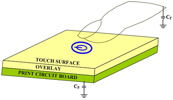
The sensor parasitic capacitance is called CP. When fingers touch or approach the sensor's surface, it forms a simple parallel plate capacitor with the sensor pad through the overlay. The result is called finger capacitance CF, it increases the measured capacitance CS: CS = CP + CF.
In the initial state, an amount of charge is built-up on an untouched sensor to set the sensor's reference level, CS = CP. As the finger makes contact with the sensor, it couples with the electric field of the sensor. This results in a drop of that sensor's charge - since a portion of that charge is drained off through the finger to ground. Further charge transfers (conversions) from that sensor result in a reduced signal level compared to the untouched state.
Capacitive touch controller as CapTouch System shows is implemented by oversampling a high sensitivity ADC which only requires 1-pin per channel. The ADC will capture the voltage of both the reference level (baseline) and the signal level and transform them into digital raw data. If the difference between the reference level and the signal level is greater than the user-determined finger touch threshold, a touch is detected, and at the same time, a touch interrupt will be sent to the MCU to wake up the top system or other operations.
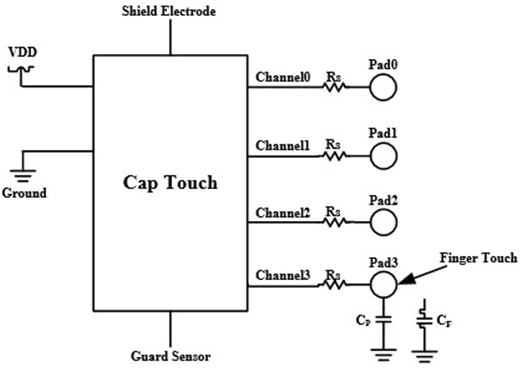
CapTouch System
Capacitive touch controller supports up to 4 capacitive sensing inputs, which offers a wide detection range of capacitance, and best-in-class liquid tolerance. With the smart calibration function enabled, all channels' sensitivity or thresholds could be adjusted individually according to different noise environments. Both of baseline value and the absolute finger touch threshold value will be calibrated automatically to adapt to environmental variation. The capacitive controller offers an adjustable scan period, resulting in lower power consumption.
Feature List
Support 4 capacitive sensor channels.
Support wide parasitic capacitance range for each channel: 5~45pF (5uA sensitivity).
Support both finger touch detection and proximity detection.
Programmable enable/disable for each channel.
Adjustable sensitivity for each channel: 0.25uA~15.75uA.
Adjustable baseline and touch threshold (both difference and absolute value) for each channel.
Support liquid tolerance: guard sensor.
Programmable channel scan mode.
Auto scan mode: hardware automatically scans every enabled channel in sequence.
Automatic environment sensor capacitance tracking and calibration (ETC).
Support interrupt control.
Low power consumption.
Block Diagram
Here is the overall IPs block diagram for CapTouch IP¹, which including 'PAD/PINMUX' for IO function configuration, 'CapTouch IP' for CapTouch protocol.
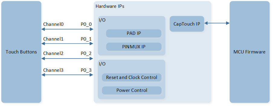
System Block Diagram of CapTouch
Channel Pin Location
Channel 0: P0_0
Channel 1: P0_1
Channel 2: P0_2
Channel 3: P0_3
Sample Range
CapTouch sample range is related to channel sensitivity; the more sensitive the channel, the shorter the sample range. The sensitivity parameter is used to increase or decrease the strength of the sensor signal (difference count), which means different counts for the same capacitance change. A higher value of the sensitivity setting (bias current) leads to a stronger signal from the sensors (more difference count for the same capacitance change), and also causes the decrease of the sample range. The typical sample range of CapTouch is 5~45pF when channel sensitivity is 5uA.
Environment Tracking and Calibration (ETC)
Sensor capacitance changes all the time according to environmental variations, such as temperature, moisture, overlay changes, or other slight environmental noise. The ETC module is built for tracking and calibration with environmental variation. The ETC function operates all the time during low power mode. The ETC system tracks the sensor capacitance change by period and updates the baseline and touch threshold based on the ETC automatic update algorithm.
There is no need for an extra scan operation except an active mode scan operation. ETC auto-tunes all the parameters of the ETC module, it works by capturing and comparing the data of the scan operation, and making a decision to update the baseline and absolute threshold or not.
Manual tuning of ETC parameters is also supported to meet different noise environments or special applications.
Touch Judgement Mode (with ETC Function Enable)
After ADC finishes data processing, decision logic will finish the following operations:
Data average operation.
Make subtraction operations of the average sample data and baseline.
Compare difference data with difference threshold.
If the difference data is larger than the difference threshold, touch or proximity is detected.
Auto Scan Mode
Hardware will scan every enabled channel in sequence during one scan period. For example, if channel 2 is disabled, then hardware will scan channel 0->1->3 once each scan period. The auto scan mode flow as Auto Scan Mode Flow Chart shows.
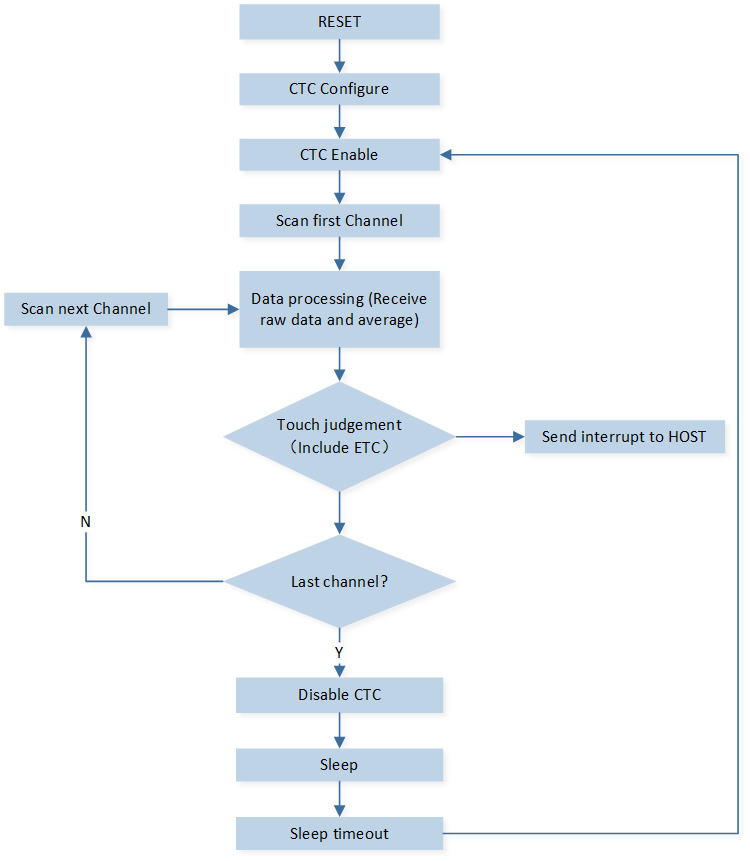
Auto Scan Mode Flow Chart
Scan Period
CapTouch scan period consists of active time and sleep time. Both the active time and sleep time can be set individually for different applications. The scan period as Schematic Diagram of Scan Period shows.
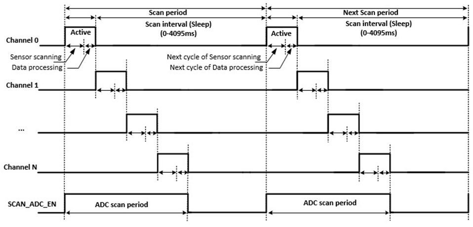
Schematic Diagram of Scan Period
Active Time
The active time of CapTouch is defined by ADC scan sample number. CapTouch averages the sample raw data of capture ADC for best accuracy and noise immunity.
Sleep Time
After all of these operations for each channel, the channel enters the sleep period, and another channel begins to scan and process data. After 4 channels of scanning and data processing are finished, capture ADC power is off, and the CapTouch system enters an ultra-low power state until the next cycle of sensor scanning. During the sleep period, all channels are still enabled, and MCU uses clock gating to save power. Each channel could be disabled while a sensor error is detected or in other situations.
Baseline Auto-Initialization
The baseline initial value is 0x0 when CapTouch function enables, CapTouch will initialize baseline value automatically with ETC function and baseline initial function both are enabled. Hardware will set the baseline with average of ADC raw code. After that, hardware will enter normal scan mode (ETC scan and judge operation).
Noise Threshold
The environmental negative noise threshold means the maximum capacitance change of raw data that is still considered an environmental change. CapTouch system supports 2 noise thresholds: positive noise threshold and negative noise threshold for optimal calibration. Both of the two noise thresholds are individually adjustable for each channel.
Environmental noise usually changes slightly and slowly. Most of the noise average data ranges from 0~50, less than 40% * touch threshold even when Bluetooth or other RF transmissions occur beside the CapTouch device. The recommended value of noise threshold is 40% * touch threshold.
Specific operations take place while a signal changes significantly, which is larger than the noise threshold. For example, when a finger touches the sensor surface, glass or plastic overlay causes the difference data (baseline - signal) to be larger than the negative noise threshold. Glass or plastic being removed from the sensor surface or a finger released after CapTouch initiation both cause the difference data (signal - baseline) to be larger than the positive noise threshold. All of these operations are not normal environment noise variations.
CapTouch sends P_ENT interrupt to the host while the difference (signal - baseline) is larger than the positive noise threshold. The host needs to initialize the baseline when P_ENT is detected. CapTouch instructs the ETC module to ignore the ETC update operation automatically when the difference data (baseline - signal) is larger than the negative noise threshold.
Both noise thresholds need tuning for different applications and noise environments.
Fast Mode
To improve response time, the scan period can become smaller after detecting ADC raw data lower than the threshold. The smaller interval makes for a faster response time and higher power consumption.
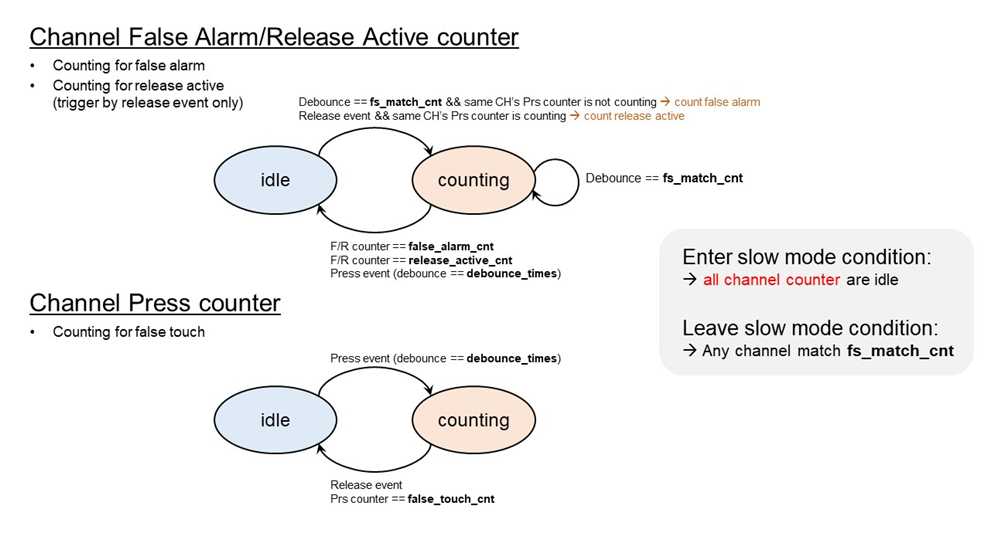
Channel False Alarm and Release Active Counter
-
Fs Match Counter
In idle mode, count how many scans meet the threshold condition. When
fs_match_cntmeets the setting, the scan interval changes from slow mode to fast mode. When settingfs_match_cnt= 0, it will always be in slow mode. -
False Alarm Counter
Counting for false alarms. When
fs_match_cntmeets anddebounce_cntdoesn't meet, the false alarm counter will count the scans in fast mode. After the false alarm counter meets, it returns to the idle state (slow interval). -
Release Active Counter
Counting for release active (triggered by the release active event). After the release active event, counting scans in fast mode. After the release active counter meets, it returns to the idle state (slow mode).
Channel Press Counter
-
False Touch Counter
Counter for false touch. It starts after the debounce counter meets the setting. After the false touch counter triggers, it is forced to return to the idle state to prevent extra power consumption.
-
Fast Touch Counter
Counting how many scans meet threshold conditions in fast mode. Calculate the press time according to this counter.
Fast Mode Control Flow Chart
Power Manager
CapTouch can be enabled to wake up the system by calling CapTouch_ChWakeupCmd().
If enable wakeup from power down mode, pmu_set_clk_32k_power_in_powerdown is required to be called for keep 32K clock.
See Also
Please refer to the relevant API Reference: