IR

IR Demo Code Support List

This chapter introduces the details of the IR demo code.

IR Demo for Polling Mode

The description of IR demo code 1 is shown in the following table.

IR Demo Code 1 Description

Demo 1

ir_send_polling_mode_demo.c

Sample Purpose

Demonstrate how IR sends data by polling mode.

File Path

sdk\src\sample\io_demo\ir\send\ir_send_polling_mode_demo.c

Function Entry

ir_send_polling_mode_demo()

Hardware Connection

Connect M2_2 to channel 0 of the logic analyzer.

Pin Definition

#define IR_SEND_PIN     P2_2

Expected Result

The waveform displayed by channel 0 of the logic analyzer is shown in IR Demo Code 1 Expected Result Diagram.

The expected result of IR demo code 1 is shown in the figure below.

../../../_images/IR_Demo_1_Expected_Result_Diagram.png

IR Demo Code 1 Expected Result Diagram

IR Demo for TX Data in Interrupt Mode

The description of IR demo code 2 is shown in the following table.

IR Demo Code 2 Description

Demo 2

ir_send_interrupt_demo.c

Sample Purpose

Demonstrate how IR sends data by interrupt mode.

File Path

sdk\src\sample\io_demo\ir\send\ir_send_interrupt_demo.c

Function Entry

ir_send_interrupt_demo()

Hardware Connection

Connect M2_2 to channel 0 of the logic analyzer.

Pin Definition

#define IR_SEND_PIN     P2_2

Expected Result

The waveform displayed by channel 0 of the logic analyzer is shown in IR Demo Code 2 Expected Result Diagram.

The expected result of IR demo code 2 is shown in the figure below.

../../../_images/IR_Demo_2_Expected_Result_Diagram.png

IR Demo Code 2 Expected Result Diagram

IR Demo for RX Data in Interrupt Mode

The description of IR demo code 3 is shown in the following table.

IR Demo Code 3 Description

Demo 3

ir_receive_demo.c

Sample Purpose

Demonstrate how IR receives data by interrupt mode.

File Path

sdk\src\sample\io_demo\ir\receive\ir_receive_demo.c

Function Entry

ir_receive_demo()

Hardware Connection

Connect M0_2 to the receiving end of the IR transceiver module, connect VCC of EVB to VCC of IR transceiver module, and connect GND of EVB to GND of IR transceiver module.

Pin Definition

#define IR_RECV_PIN     P0_2

Expected Result

Send IR data to the IR transceiver module by IR remote control. The received data is stored in array IR_DataStruct.irBuf.

IR Demo for Pulse Detection

The description of IR demo code 4 is shown in the following table.

IR Demo Code 4 Description

Demo 4

ir_pulse_detection_demo.c

Sample Purpose

Demonstrate the pulse detection of duty and frequency of a PWM with IR.

File Path

sdk\src\sample\io_demo\ir\pulse_detection\ir_pulse_detection_demo.c

Function Entry

ir_pulse_detection_demo()

Hardware Connection

Connect M2_1 to PWM output.

Pin Definition

#define IR_RECV_PIN     P2_1

Expected Result

Print PWM frequency, high level count, and low level count information in Debug Analyzer.

IR Demo for Encoding and Decoding by NEC Protocol

The description of IR demo code 5 is shown in the following table.

IR Demo Code 5 Description

Demo 5

ir_nec_protocol.c

ir_nec_protocol.h

Sample Purpose

Demonstrates encoding and decoding data by NEC protocol.

File Path

sdk\src\sample\io_demo\ir\protocol\ir_nec_protocol.c

sdk\src\sample\io_demo\ir\protocol\ir_nec_protocol.h

Function Entry

IR_NECEncode()

IR_NECDecode()

Expected Result

Call the API IR_NECEncode() and encode the data by the NEC protocol. Call the API IR_NECDecode() and decode the data by the NEC protocol.

Functional Overview

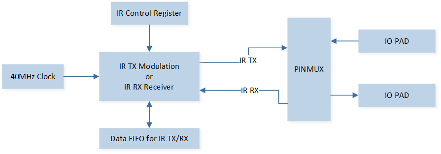
The infrared module can realize infrared wireless communication with adjacent devices.

../../../_images/Schematic_Diagram_of_IR_Module.png

Schematic Diagram of IR Module

Feature List

  • Configurable carrier frequency.

  • Configurable carrier duty cycle.

  • Configurable carrier on/off time.

  • Hardware controlled waveform output.

  • Support any infrared communication protocol.

  • Support GDMA.

  • RX mode and TX mode cannot work at the same time.

  • IR module must be reset when switching between RX mode and TX mode.

TX

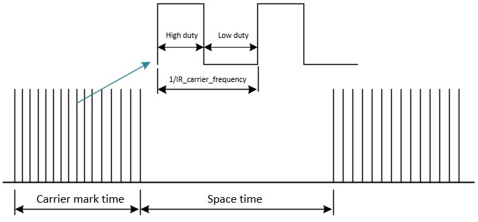
The schematic diagram of IR TX is shown in the figure below.

../../../_images/Schematic_Diagram_of_IR_TX.jpg

Schematic Diagram of IR TX

Program Examples

Send Data Operation Flow

Initialization Flow

IR initialization flow is shown in the following figure.

../../../_images/IR_Initialization_Flow_Chart.png

IR Initialization Flow Chart

The codes below demonstrate the IR initialization flow.

/* Enable IR clock */
RCC_PeriphClockCmd(APBPeriph_IR, APBPeriph_IR_CLOCK, ENABLE);

/* Initialize IR */
IR_InitTypeDef IR_InitStruct;
IR_StructInit(&IR_InitStruct);
IR_InitStruct.IR_Freq           = 38;
IR_InitStruct.IR_DutyCycle      = 2; /* !< 1/2 duty cycle */
IR_InitStruct.IR_Mode           = IR_MODE_TX;
IR_InitStruct.IR_TxInverse      = IR_TX_DATA_NORMAL;
IR_InitStruct.IR_TxIdleLevel    = IR_IDLE_OUTPUT_LOW;
IR_InitStruct.IR_TxFIFOThrLevel = IR_TX_FIFO_THR_LEVEL;
IR_Init(&IR_InitStruct);

/* Configure NVIC */
NVIC_InitTypeDef NVIC_InitStruct;
NVIC_InitStruct.NVIC_IRQChannel = IR_IRQn;
NVIC_InitStruct.NVIC_IRQChannelPriority = 2;
NVIC_InitStruct.NVIC_IRQChannelCmd = ENABLE;
NVIC_Init(&NVIC_InitStruct);

Send Data Operation Flow

IR send data operation flow is shown in the following figure.

../../../_images/IR_Send_Data_Operation_Flow_Chart.png

IR Send Data Operation Flow Chart

The codes below demonstrate the IR send data operation flow.

/* Buffer which stores encoded data */
IR_DataTypeDef IR_DataStruct;
/* Number of data which has been sent */
uint8_t tx_count = 0;

/* Data to send */
uint8_t ir_code[2] = {0x16, 0x28};

/* Make sure TX FIFO is empty */
IR_ClearTxFIFO();

/* Encode by NEC protocol */
IR_NECEncode(38, ir_code[0], ir_code[1], &IR_DataStruct);

/* Start to send the first bytes of encoded data */
IR_SendBuf(IR_DataStruct.irBuf, IR_TX_FIFO_SIZE, DISABLE);

/* Record the number which has been sent */
tx_count = IR_TX_FIFO_SIZE;

/* Enable IR threshold interrupt. When TX FIFO offset <= threshold value, trigger interrupt*/
IR_INTConfig(IR_INT_TF_LEVEL, ENABLE);

/* Must fill TX FIFO first */
IR_Cmd(IR_MODE_TX, ENABLE);

Interrupt Handle Flow

IR interrupt handle flow is shown in the following figure.

../../../_images/IR_send_flow_in_interrupt_handler.png

IR Send Flow in Interrupt Handler

The codes below demonstrate the IR interrupt handle flow.

void ir_handler(void)
{
   /* Continue to send by interrupt */
   if (IR_GetINTStatus(IR_INT_TF_LEVEL) == SET)
   {
      IR_MaskINTConfig(IR_INT_TF_LEVEL, ENABLE);
      /* The remaining data is larger than the TX FIFO length */
      if ((NEC_LENGTH - tx_count) >= IR_TX_FIFO_SIZE)
      {
            IR_SendBuf(IR_DataStruct.irBuf + tx_count, (IR_TX_FIFO_SIZE - IR_TX_FIFO_THR_LEVEL), DISABLE);
            tx_count += (IR_TX_FIFO_SIZE - IR_TX_FIFO_THR_LEVEL);
      }
      else if ((NEC_LENGTH - tx_count) > 0)
      {
            /* The remaining data is less than the TX FIFO length */

            /*  Configure TX threshold level to zero and trigger interrupt when TX FIFO is empty */
            IR_SetTxThreshold(0);
            IR_SendBuf(IR_DataStruct.irBuf + tx_count, NEC_LENGTH - tx_count, ENABLE);
            tx_count += (NEC_LENGTH - tx_count);
      }
      else
      {
            /* Tx completed */
            uint8_t event = IO_DEMO_EVENT_IR_TX;
            /* Disable IR tx empty interrupt */
            IR_INTConfig(IR_INT_TF_LEVEL, DISABLE);
            tx_count = 0;
            if (os_msg_send(io_queue_handle, &event, 0) == false)
            {
               IO_PRINT_ERROR0("ir_handler: Send queue error");
            }
      }

      /* Clear threshold interrupt */
      IR_ClearINTPendingBit(IR_INT_TF_LEVEL_CLR);
      /* Unmask IR interrupt */
      IR_MaskINTConfig(IR_INT_TF_LEVEL, DISABLE);
   }
}

Receive Data Operation Flow

Initialization Flow

IR initialization flow is shown in the following figure.

../../../_images/IR_Initialization_Flow_Chart_2.png

IR Initialization Flow Chart

The codes below demonstrate the IR initialization operation flow.

/* Enable IR clock */
RCC_PeriphClockCmd(APBPeriph_IR, APBPeriph_IR_CLOCK, ENABLE);

/* Initialize IR */
IR_InitTypeDef IR_InitStruct;
IR_StructInit(&IR_InitStruct);

IR_InitStruct.IR_Freq               = 38;/* IR carrier frequency is 38KHz */
IR_InitStruct.IR_DutyCycle          = 2;/* Duty ratio = 1/IR_DutyCycle */
IR_InitStruct.IR_Mode               = IR_MODE_RX;/* IR receiving mode */
IR_InitStruct.IR_RxStartMode        = IR_RX_AUTO_MODE;
IR_InitStruct.IR_RxFIFOThrLevel     = IR_RX_FIFO_THR_LEVEL; /* Configure RX FIFO threshold level to trigger IR_INT_RF_LEVEL interrupt */
IR_InitStruct.IR_RxFIFOFullCtrl     = IR_RX_FIFO_FULL_DISCARD_NEWEST;/* Discard the latest received data if RX FIFO is full */
IR_InitStruct.IR_RxTriggerMode      = IR_RX_RISING_EDGE;/* Configure trigger type */
IR_InitStruct.IR_RxFilterTime       = IR_RX_FILTER_TIME_50ns;/* If high to low or low to high transition time <= 50ns, filter it out. */
IR_InitStruct.IR_RxCntThrType       = IR_RX_Count_Low_Level;/* IR_RX_Count_Low_Level is counting low level */
IR_InitStruct.IR_RxCntThr           = 0x23a;/* Configure RX counter threshold. You can use it to decide to stop receiving IR data */
IR_Init(&IR_InitStruct);

/* Enable IR threshold interrupt. When RX FIFO offset >= threshold value, trigger interrupt*/
/* Enable IR counter threshold interrupt to stop receiving data */
IR_INTConfig(IR_INT_RF_LEVEL | IR_INT_RX_CNT_THR, ENABLE);
IR_MaskINTConfig(IR_INT_RF_LEVEL | IR_INT_RX_CNT_THR, DISABLE);

/* Configure NVIC */
NVIC_InitTypeDef NVIC_InitStruct;
NVIC_InitStruct.NVIC_IRQChannel = IR_IRQn;
NVIC_InitStruct.NVIC_IRQChannelPriority = 2;
NVIC_InitStruct.NVIC_IRQChannelCmd = ENABLE;
NVIC_Init(&NVIC_InitStruct);

IR_ClearRxFIFO();
IR_Cmd(IR_MODE_RX, ENABLE);

Receive Data Operation Flow

IR receive data operation flow is shown in the following figure.

../../../_images/IR_Receive_Data_Operation_Flow_Chart.png

IR Receive Data Operation Flow Chart

The codes below demonstrate the IR receive data operation flow.

/* Wait for receiving the whole IR packets */
/* This is just a demo. You can send message from IR interrupt handler */
while (rx_count <= NEC_LENGTH - 5) {;};

if (IR_SUCCEED != IR_NECDecode(38, &address, &cmd, &IR_DataStruct))
{
   // Decoding error!
}
else
{
   // Decoding success!
}

Interrupt Handle Flow

IR interrupt handle flow is shown in the following figure.

../../../_images/IR_receive_flow_in_interrupt_handler.png

IR Receive Flow in Interrupt Handler

The codes below demonstrate the IR interrupt handle flow.

void ir_handler(void)
{
   uint16_t len = 0;

   /* Receive by interrupt */
   if (IR_GetINTStatus(IR_INT_RF_LEVEL) == SET)
   {
      IR_MaskINTConfig(IR_INT_RF_LEVEL, ENABLE);
      len = IR_GetRxDataLen();
      IR_ReceiveBuf(IR_DataStruct.irBuf + rx_count, len);
      IR_DataStruct.bufLen += len;
      rx_count += len;
      IR_ClearINTPendingBit(IR_INT_RF_LEVEL_CLR);
      IR_MaskINTConfig(IR_INT_RF_LEVEL, DISABLE);
   }

   /* Stop to receive IR data */
   if (IR_GetINTStatus(IR_INT_RX_CNT_THR) == SET)
   {
      IR_MaskINTConfig(IR_INT_RX_CNT_THR, ENABLE);
      /* Read remaining data */
      len = IR_GetRxDataLen();
      IR_ReceiveBuf(IR_DataStruct.irBuf + rx_count, len);
      IR_DataStruct.bufLen += len;
      rx_count += len;
      IR_ClearINTPendingBit(IR_INT_RX_CNT_THR_CLR);
      IR_MaskINTConfig(IR_INT_RX_CNT_THR, DISABLE);
   }
}