Digital Microphone
This example code collects DMIC data and encodes it into PCM voice data using the CODEC.
DMIC collects analog voice data, which is encoded by CODEC and sent to the I2S receive FIFO. The data is then transferred to UART using GDMA.
On the PC side, a serial assistant receives the data transmitted by UART. Audio parsing software is used to analyze the data and play the recorded voice. In this example, the audio parsing software used is Audacity.
Requirements
For requirements, please refer to the Requirements.
In addition, you need to install PuTTY or UartAssist serial assistant tools and audio parsing tools like Audacity on the PC terminal.
Wiring
Connect the DMIC module to the EVB, connecting P2_2 to CLK and P2_3 to DATA.
Connect the FT232 module to the EVB to receive UART data, connecting P3_2 to RXD, and P3_3 to TXD.
Building and Downloading
For building and downloading, please refer to the Building and Downloading.
Experimental Verification
Preparation Stage
Start the PC terminal with PuTTY or UartAssist, use ASCII to receive data, open the UART COM port, and make the following UART settings:
Baud rate: 3000000
8 data bits
1 stop bit
No parity
No hardware flow control
Set the output data bytes to redirect to a file.
Start the audio parsing software and select the parsing format according to the settings in CODEC. In this example, you can refer to the following Audacity settings.
Encoding: 16-bit PCM
Endianness: Little Endian
Channels: 1 channel
Sample rate: 1600 Hz
Testing Stage
From start to finish of recording, the collected voice data is encoded by Codec as PCM data and sent to the PC terminal via UART.
Use the audio parsing software to view the decoded voice waveform and play the voice.
Code Overview
This section introduces the code and process description for initialization and corresponding function implementation in the sample.
Source Code Directory
The directory for project file and source code are as follows:
Project directory:
sdk\samples\peripheral\codec\dmic\projSource code directory:
sdk\samples\peripheral\codec\dmic\src
Initialization
The initialization flow for peripherals can refer to Initialization Flow in General Introduction.
The initialization process includes initializing the CODEC / UART / I2S / GDMA modules as follows.
-
Call
Pad_Config()andPinmux_Config()to configure the PAD and PINMUX of the corresponding pins. The I2S pin multiplexing functions are BCLK_SPORT0, LRC_RX_SPORT0, SDI_CODEC_SLAVE, and SDO_CODEC_SLAVE.void board_codec_init(void) { Pad_Config(DMIC_MSBC_CLK_PIN, PAD_PINMUX_MODE, PAD_IS_PWRON, PAD_PULL_NONE, PAD_OUT_DISABLE,PAD_OUT_LOW); Pad_Config(DMIC_MSBC_DAT_PIN, PAD_PINMUX_MODE, PAD_IS_PWRON, PAD_PULL_NONE, PAD_OUT_DISABLE,PAD_OUT_LOW); Pinmux_Config(DMIC_MSBC_CLK_PIN, DMIC1_CLK); Pinmux_Config(DMIC_MSBC_DAT_PIN, DMIC1_DAT); Pad_Config(CODEC_BCLK_PIN, PAD_PINMUX_MODE, PAD_IS_PWRON, PAD_PULL_NONE, PAD_OUT_ENABLE,PAD_OUT_LOW); Pad_Config(CODEC_LRCLK_PIN, PAD_PINMUX_MODE, PAD_IS_PWRON, PAD_PULL_NONE, PAD_OUT_ENABLE, PAD_OUT_LOW); Pad_Config(CODEC_TX_PIN, PAD_PINMUX_MODE, PAD_IS_PWRON, PAD_PULL_NONE, PAD_OUT_ENABLE, PAD_OUT_LOW); Pad_Config(CODEC_RX_PIN, PAD_PINMUX_MODE, PAD_IS_PWRON, PAD_PULL_NONE, PAD_OUT_ENABLE, PAD_OUT_LOW); Pinmux_Config(CODEC_BCLK_PIN, BCLK_SPORT0); Pinmux_Config(CODEC_LRCLK_PIN, LRC_RX_SPORT0); Pinmux_Config(CODEC_TX_PIN, SDI_CODEC_SLAVE); Pinmux_Config(CODEC_RX_PIN, SDO_CODEC_SLAVE); }
For the initialization configuration of UART, I2S, and GDMA peripherals, refer to the amic initialize.
-
Initialize the CODEC peripheral.
Call
RCC_PeriphClockCmd()to enable the CODEC clock.Execute
CODEC_StructInit()andCODEC_Init()to initialize the CODEC peripheral. The configuration parameters for the CODEC initialization are as follows:
CODEC Hardware Parameters |
Setting in the |
CODEC |
|---|---|---|
Mic Type |
||
DMIC Clock |
||
SampleRate |
||
DMIC Data Latch |
||
I2S Data Format |
||
I2S Channel Len |
||
I2S Data Width |
||
I2S Channel Sequence |
Call
I2S_Cmd()to enable the I2S receive mode. CallGDMA_Cmd()to enable GDMA transfer.
Functional Implementation
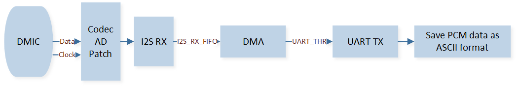
After DMIC collects the voice data, the CODEC module AD conversion puts the voice data into the I2S RX FIFO. The data in the I2S RX FIFO is then transferred to the UART TX FIFO via GDMA. In the serial assistant, save the data sent by UART to a file, and parse the file data using audio parsing software. The data transmission order in each module is shown in the figure below.
Data Transfer Module (DMIC)
-
When the GDMA transfer amount reaches the set BlockSize, it triggers the
GDMA_INT_Transferinterrupt. As the audio data undergoes AD conversion via CODEC, the data size is relatively large and a single GDMA transfer cannot meet the demand. The source address, destination address, and BlockSize are reset in the interrupt handler, and GDMA transfer is re-enabled to ensure the transmission of a large amount of data continuously.GDMA_SetSourceAddress(GDMA_Channel_DMIC, (uint32_t)(&(I2S0->I2S_RX_FIFO_RD_ADDR))); GDMA_SetDestinationAddress(GDMA_Channel_DMIC, (uint32_t)(&(UART5->UART_RBR_THR))); GDMA_SetBufferSize(GDMA_Channel_DMIC, AUDIO_FRAME_SIZE / 4); GDMA_ClearINTPendingBit(GDMA_Channel_DMIC_NUM, GDMA_INT_Transfer); GDMA_Cmd(GDMA_Channel_DMIC_NUM, ENABLE);
See Also
Please refer to the relevant API Reference: