LoopBack
This sample demonstrates communication between I2C master and slave using interrupt. Meanwhile, the master and the slave are interconnected to achieve lookback. Samples of its three communication modes are as follows:
Communication |
Brief Introduction |
Macros in Configuration |
|---|---|---|
The master sends data and the slave receives data. |
Set |
|
The master receives data and the slave sends data. |
Set |
|
The master sends data and then receives data. |
Set |
In this sample, I2C0 is configured as the master, and I2C1 is configured as the slave.
Requirements
For requirements, please refer to the Requirements.
Wiring
Connect P4_0 (master SCL) to P4_2 (slave SCL), P4_1 (master SDA) to P4_3 (slave SDA) on the EVB.
Note
The frequency of SCL is influenced by both the pull-up resistor and the wire capacitance. Therefore, it is strongly recommended to choose appropriate pull-up resistors to make the frequency accurate. This sample need connect 2.2 kΩ pull-up resistors.
The connection schematic of the pull-up resistor is shown below:
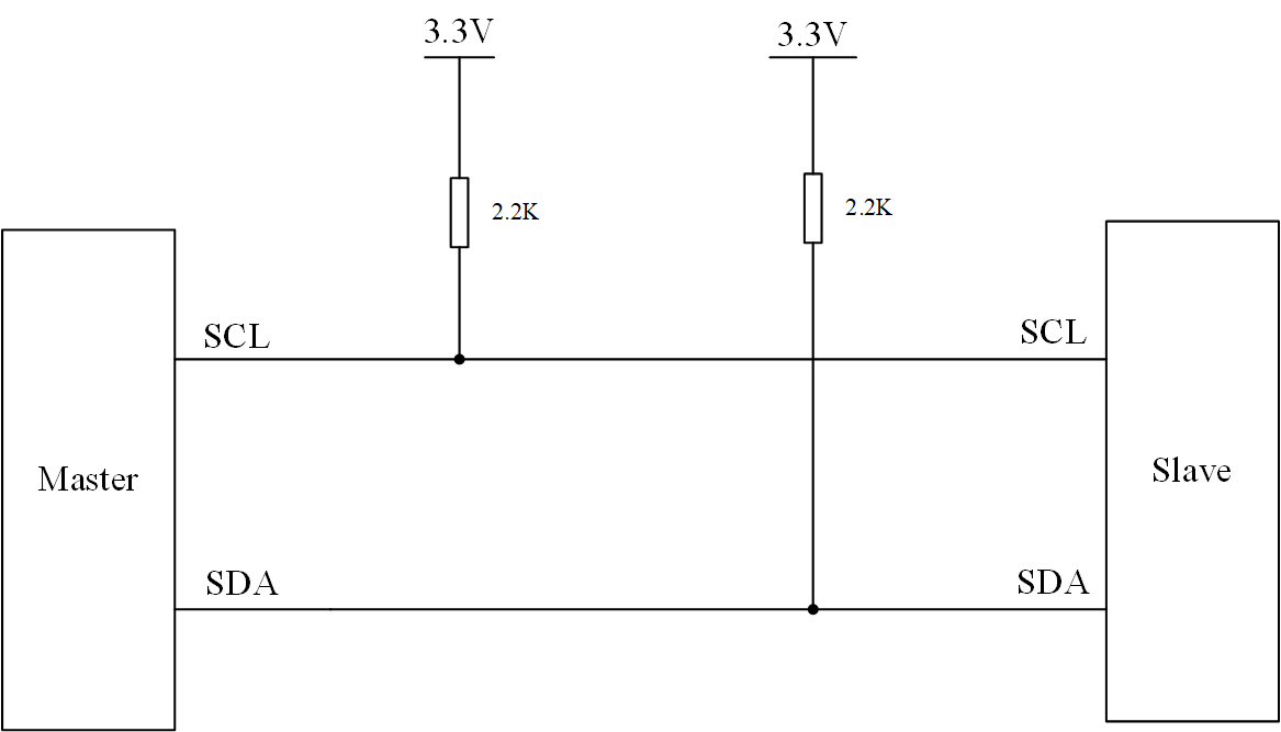
I2C pull-up resistor schematic
Configurations
-
The following macros can be configured to modify the sample function. Note: Only one of the following three macros can be set to 1.
#define I2C_MASTER_SEND_SLAVE_RECEIVE   0       /*< Set this macro to 1 to modify the sample for master send slave receive function. */
#define I2C_MASTER_RECEIVE_SLAVE_SEND   0       /*< Set this macro to 1 to modify the sample for master receive slave send function. */
#define I2C_MASTER_REPEAT_READ          1       /*< Set this macro to 1 to modify the sample for master repeat read function. */
-
The following macros can be configured to modify pin definitions.
#define I2C0_SCL_PIN                    P4_0
#define I2C0_SDA_PIN                    P4_1

#define I2C1_SCL_PIN                    P4_2
#define I2C1_SDA_PIN                    P4_3
-
The following macros can be configured to modify the I2C data transfer length.
#define TransferLength 24 /*< Set this macro to modify the transfer length. */
Building and Downloading
For building and downloading, please refer to the Building and Downloading.
Experimental Verification
Master Send Slave Receive
-
After the EVB starts, the master sends 24 bytes of data ranging from 0 to 23. When the master completing sending data, the
I2C_INT_STOP_DETinterrupt is triggered and interrupt log information is printed.I2C0 Stop signal detected
-
When the data received from the slave reaches the set threshold level(set to 8 in this sample), the
I2C_INT_RX_FULLinterrupt is triggered. The interrupt log information is printed and the data is received in the interrupt handler.I2C1 Rx Full detected
-
When the master completes sending data, the slave detects the stop signal and triggers the
I2C_INT_STOP_DETinterrupt. The interrupt log information is printed, and the remaining data is received. Meanwhile, the data length and data is printed in the interrupt handler.I2C1 Stop signal detected Slave Recv Date Lenth = 24 I2C1_Slave_ReceiveData=0 ... I2C1_Slave_ReceiveData=23
Master Receive Slave Send
After the EVB starts, the master device reads the expected 24 bytes data by sending a read request command to the slave device.
-
When the slave receives the read request from the master, the
I2C_INT_RD_REQinterrupt is triggered. The interrupt log information is printed, and the slave device sends 24 bytes of data, with content ranging from 10 to 33, to the master device in the interrupt handler.Enter I2C1 interrupt I2C1_INT_RD_REQ!
-
After the master device completes receiving the data, it prints the received data.
Master Read data = 10
...
Master Read data = 33
Master Repeat Read
After the EVB starts, the master device sends 4 bytes of data ranging from 1 to 4 to the slave device.
Once the master device finishes sending data, the master device reads the expected 24 bytes data by sending a read request command to the slave device.
-
When the slave receives the read request from the master, the
I2C_INT_RD_REQinterrupt is triggered. The interrupt log information is printed, and the slave device sends 24 bytes of data, with content ranging from 10 to 33, to the master device in the interrupt handler.Enter I2C1 interrupt I2C1_INT_RD_REQ!
-
After the slave device finishes sending data to the master device, the master device generates a stop signal. The slave device triggers
I2C_INT_RX_DONEandI2C_INT_STOP_DETinterrupt. And the data received in step 1 is printed in the interrupt handler.I2C1 RX_DONE detected I2C1 Stop signal detected Slave Recv Date Lenth = 4 I2C1_Slave_ReceiveData=1 I2C1_Slave_ReceiveData=2 I2C1_Slave_ReceiveData=3 I2C1_Slave_ReceiveData=4
-
After the master device finishes receiving the data, it prints the received data.
Master Repeat Read data = 10
...
Master Repeat Read data = 33
Code Overview
This section introduces the code and process description for initialization and corresponding function implementation in the sample.
Source Code Directory
The directory for project file and source code are as follows:
Project directory:
sdk\samples\peripheral\i2c\trx_loopback\projSource code directory:
sdk\samples\peripheral\i2c\trx_loopback\src
Initialization
The initialization flow for peripherals can refer to Initialization Flow in General Introduction.
-
Call
Pad_Config()andPinmux_Config()to configure the PAD and PINMUX of the corresponding pins.void board_i2c_master_init(void) { Pad_Config(I2C_MASTER_SCL_PIN, PAD_PINMUX_MODE, PAD_IS_PWRON, PAD_PULL_UP, PAD_OUT_ENABLE, PAD_OUT_HIGH); Pad_Config(I2C_MASTER_SDA_PIN, PAD_PINMUX_MODE, PAD_IS_PWRON, PAD_PULL_UP, PAD_OUT_ENABLE, PAD_OUT_HIGH); Pinmux_Config(I2C_MASTER_SCL_PIN, I2C0_CLK); Pinmux_Config(I2C_MASTER_SDA_PIN, I2C0_DAT); } void board_i2c_slave_init(void) { Pad_Config(I2C_SLAVE_SCL_PIN, PAD_PINMUX_MODE, PAD_IS_PWRON, PAD_PULL_UP, PAD_OUT_ENABLE, PAD_OUT_HIGH); Pad_Config(I2C_SLAVE_SDA_PIN, PAD_PINMUX_MODE, PAD_IS_PWRON, PAD_PULL_UP, PAD_OUT_ENABLE, PAD_OUT_HIGH); Pinmux_Config(I2C_SLAVE_SCL_PIN, I2C1_CLK); Pinmux_Config(I2C_SLAVE_SDA_PIN, I2C1_DAT); }
Call
RCC_PeriphClockCmd()to enable the I2C clock.-
Initialize the I2C peripheral:
Define the
I2C_InitTypeDeftypeI2C_InitStruct, and callI2C_StructInit()to pre-fillI2C_InitStructwith default values.Modify the
I2C_InitStructparameters as needed. The initialization parameter configurations for I2C0 and I2C1 are shown in the table below. CallI2C_Init()to initialize the I2C peripheral.
I2C Hardware Parameters |
Setting in the |
I2C0(Master) |
I2C1(Slave) |
|---|---|---|---|
Clock(Hz) |
100000 |
100000 |
|
Device role (I2C master or I2C slave) |
|||
Address mode (7bits/ 10bits mode) |
|||
Slave address |
0x50 |
0x50 |
|
Rx threshold level |
8 |
8 |
|
Auto ACK enable |
Call
I2C_Cmd()to enable I2C peripheral.
Functional Implementation
Master Send Slave Receive
The flow for master send slave receive is shown in the figure:
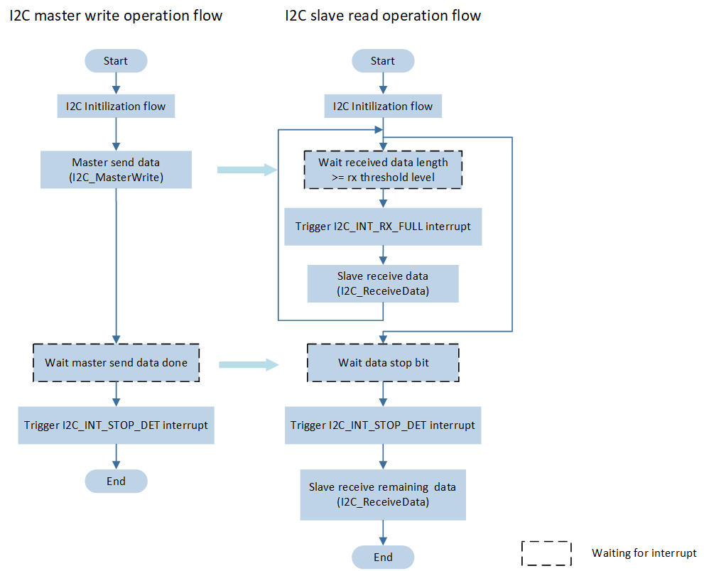
I2C Master send slave receive flow
-
Call
I2C_INTConfig()to configure the corresponding I2C interrupt and NVIC. For NVIC configuration, refer to Interrupt Configuration.void nvic_i2c_config(void) { ... #if I2C_MASTER_SEND_SLAVE_RECEIVE I2C_INTConfig(I2C0, I2C_INT_STOP_DET, ENABLE); I2C_INTConfig(I2C1, I2C_INT_RX_FULL, ENABLE); I2C_INTConfig(I2C1, I2C_INT_STOP_DET, ENABLE); I2C_INTConfig(I2C1, I2C_INT_RX_DONE, ENABLE); #endif ... /* Config I2C interrupt */ NVIC_InitTypeDef NVIC_InitStruct; ... }
The master call
I2C_MasterWrite()to send data to the slave.When the data received from the slave reaches the set threshold level, the
I2C_INT_RX_FULLinterrupt is triggered. In the slave interrupt handler, callI2C_ReceiveData()to receive data.-
When the master completes sending data, the slave detects the stop signal and triggers the slave
I2C_INT_STOP_DETinterrupt. In the slave interrupt function, callI2C_ReceiveData()to receive the remaining data.void I2C1_Handler(void) { ... if (I2C_GetINTStatus(I2C1, I2C_INT_STOP_DET) == SET) { ... lenth = I2C_GetRxFIFOLen(I2C1); for (uint32_t i = 0; i < lenth; i++) { I2C_Rev_Data[I2C_Rev_Index++] = I2C_ReceiveData(I2C1); } I2C_Rev_Data_Lenth += lenth; I2C_ClearINTPendingBit(I2C1, I2C_INT_STOP_DET); ... } ... if (I2C_GetINTStatus(I2C1, I2C_INT_RX_FULL) == SET) { lenth = I2C_GetRxFIFOLen(I2C1); /*read I2C data*/ for (uint32_t i = 0; i < lenth; i++) { I2C_Rev_Data[I2C_Rev_Index++] = I2C_ReceiveData(I2C1); } I2C_Rev_Data_Lenth += lenth; I2C_ClearINTPendingBit(I2C1, I2C_INT_RX_FULL); } }
Master Receive Slave Send
The flow for master receive slave send is shown in the figure:
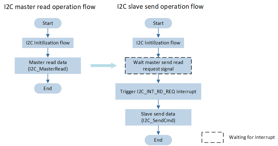
I2C master receive slave send flow
-
Call
I2C_INTConfig()to configure the corresponding I2C interrupt and NVIC. For NVIC configuration, refer to Interrupt Configuration.void nvic_i2c_config(void) { ... #if I2C_MASTER_RECEIVE_SLAVE_SEND I2C_INTConfig(I2C1, I2C_INT_RD_REQ, ENABLE); #endif ... /* Config I2C interrupt */ NVIC_InitTypeDef NVIC_InitStruct; ... }
The master calls
I2C_MasterRead()to read the data by sending a read request command to the slave device.-
When the slave receives the read request from the master, the
I2C_INT_RD_REQinterrupt is triggered. In the slave interrupt handler, callI2C_SendCmd()to send data to the master.void I2C1_Handler(void) { uint8_t send_data_buffer[100]; for (uint32_t i = 0; i < TransferLength; i++) { send_data_buffer[i] = i + 10; } if (I2C_GetINTStatus(I2C1, I2C_INT_RD_REQ) == SET) { for (uint32_t i = 0; i < TransferLength; i++) { I2C_SendCmd(I2C1, I2C_WRITE_CMD, send_data_buffer[i], DISABLE); } I2C_ClearINTPendingBit(I2C1, I2C_INT_RD_REQ); } ... }
Master Repeat Read
The master device executes the process of sending first and then receiving, the flow is shown in the figure:
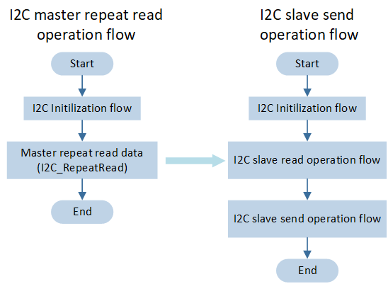
I2C master repeat read flow
-
Call
I2C_INTConfig()to configure the corresponding I2C interrupt and NVIC. For NVIC configuration, refer to Interrupt Configuration.void nvic_i2c_config(void) { ... #if I2C_MASTER_REPEAT_READ I2C_INTConfig(I2C0, I2C_INT_STOP_DET, ENABLE); I2C_INTConfig(I2C1, I2C_INT_RX_FULL, ENABLE); I2C_INTConfig(I2C1, I2C_INT_STOP_DET, ENABLE); I2C_INTConfig(I2C1, I2C_INT_RX_DONE, ENABLE); I2C_INTConfig(I2C1, I2C_INT_RD_REQ, ENABLE); #endif ... /* Config I2C interrupt */ NVIC_InitTypeDef NVIC_InitStruct; ... }
The master calls
I2C_RepeatRead(), sendstx_datato the slave, and receivesrx_datafrom the slave .When the slave device receives a read request from the master device, the
I2C_INT_RD_REQinterrupt is triggered. In the interrupt handler, callsI2C_SendCmd()to send data to the master device.-
After the slave device completes sending data to the master device, the master device generates a stop signal. The slave device triggers the
I2C_INT_RX_DONEandI2C_INT_STOP_DETinterrupts, and in the interrupt handler, callsI2C_ReceiveData()to receive data."void I2C1_Handler(void) { uint16_t lenth; uint8_t send_data_buffer[100]; for (uint32_t i = 0; i < TransferLength; i++) { send_data_buffer[i] = i + 10; } if (I2C_GetINTStatus(I2C1, I2C_INT_RD_REQ) == SET) { for (uint32_t i = 0; i < TransferLength; i++) { I2C_SendCmd(I2C1, I2C_WRITE_CMD, send_data_buffer[i], DISABLE); } I2C_ClearINTPendingBit(I2C1, I2C_INT_RD_REQ); } if (I2C_GetINTStatus(I2C1, I2C_INT_STOP_DET) == SET) { /*read I2C receive data*/ lenth = I2C_GetRxFIFOLen(I2C1); for (uint32_t i = 0; i < lenth; i++) { I2C_Rev_Data[I2C_Rev_Index++] = I2C_ReceiveData(I2C1); } I2C_Rev_Data_Lenth += lenth; I2C_ClearINTPendingBit(I2C1, I2C_INT_STOP_DET); ... } if (I2C_GetINTStatus(I2C1, I2C_INT_RX_DONE) == SET) { DBG_DIRECT("I2C1 RX_DONE detected"); I2C_ClearINTPendingBit(I2C1, I2C_INT_RX_DONE); } ... }
See Also
Please refer to the relevant API Reference: