PWM
This sample uses TIM to implement the PWM function with a period of 0.1s and a duty cycle of 50%.
To facilitate observation, P0_1 (LED0) is used as the PWM output to achieve the blinking of LED0.
Connect P0_1 to the logic analyzer, where the PWM output waveform can be observed.
Users can modify pin information, output frequency, and whether to dynamically change the frequency through different macro configurations. For specific macro configurations, refer to Configurations.
Requirements
For requirements, please refer to the Requirements.
Wiring
Connect P0_1 and LED0, or connect P0_1 to the logic analyzer to observe the PWM waveform.
The LED driver circuit is shown below.
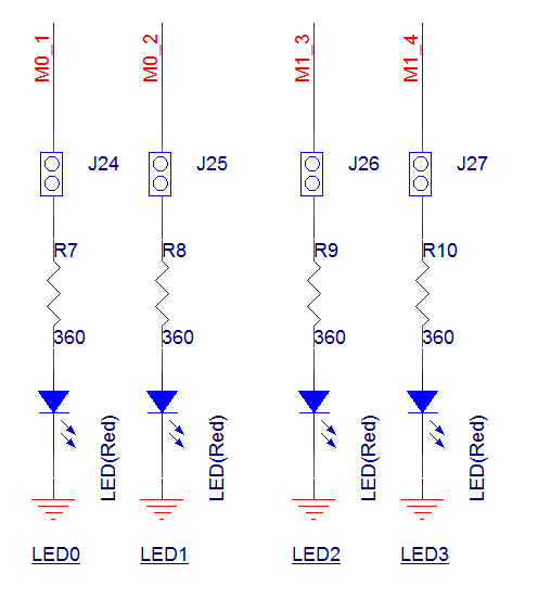
LED Driver Circuit Diagram
Configurations
-
The following macro can be configured to modify the pin definition.
#define PWM_OUT_PIN P0_1 -
The following macros can be configured to modify the frequency and duty cycle of the PWM.
#define PWM_PERIOD                        100000                                                  /*< Setting this macro to 100,000 means the output is a PWM wave with a period of 100,000 microseconds. The unit of this macro is microseconds (us). */
#define PWM_DUTY_CYCLE                    50                                                      /*< Setting this macro to 50 means the output is a PWM wave with a 50% duty cycle. */
#define PWM_HIGH_COUNT                    ((((PWM_PERIOD)*(PWM_DUTY_CYCLE*40))/100)-1)
#define PWM_LOW_COUNT                     ((((PWM_PERIOD)*((100-PWM_DUTY_CYCLE)*40))/100)-1)
-
The following macro can be configured to choose whether to enable the dynamic adjustment of the PWM frequency feature.
#define CONFIG_TIM_CHANGE_SRC_CLK 1 /*< Setting this macro to choose whether to enable the dynamic adjustment of the PWM frequency function. */
Building and Downloading
For building and downloading, please refer to the Building and Downloading.
Experimental Verification
-
When the EVB starts, observe the following log within the Debug Analyzer.
Start pwm test!
Initialization is complete. After enabling TIM, TIM begins outputting a PWM waveform. Use a logic analyzer to observe the PWM waveforms of P0_1 output or observe the blinking of LED0. P0_1 outputs a PWM wave with a period of 0.1 seconds and a duty cycle of 50%. LED0 blinks once every 0.1 seconds.

TIM PWM Output Waveform
If the macro
CONFIG_TIM_CHANGE_SRC_CLKis set to1, the clock frequency of TIM will be modified from 40MHz to 12.5MHz in the program. It can be observed that after modifying the TIM clock frequency, the PWM period changes from 100ms to 320ms, while the duty cycle remains at 50%. The PWM waveform is shown in the figure below.
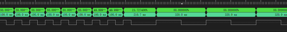
TIM PWM Output Waveform Variation with Clock Change
Code Overview
This section mainly introduces the code and process description for initialization and corresponding function implementation in the sample.
Source Code Directory
The directory for project file and source code are as follows:
Project directory:
sdk\samples\peripheral\timer\pwm\projSource code directory:
sdk\samples\peripheral\timer\pwm\src
Initialization
The initialization flow for peripherals can refer to Initialization Flow in General Introduction.
-
Call
Pad_Config()andPinmux_Config()to configure the PAD and PINMUX of the corresponding pins.void board_pwm_init(void) { Pad_Config(PWM_OUT_PIN, PAD_PINMUX_MODE, PAD_IS_PWRON, PAD_PULL_NONE, PAD_OUT_ENABLE, PAD_OUT_HIGH); Pinmux_Config(PWM_OUT_PIN, PWM_OUT_PIN_PINMUX); }
Call
RCC_PeriphClockCmd()to enable the TIM clock.-
Initialize the TIM peripheral:
Define the
TIM_TimeBaseInitTypeDeftypeTIM_InitStruct, and callTIM_StructInit()to pre-fillTIM_InitStructwith default values.Modify the
TIM_InitStructparameters as needed. The initialization parameter configurations for TIM are shown in the table below. CallTIM_TimeBaseInit()to initialize the TIM peripheral.
TIM Hardware Parameters |
Setting in the |
TIM |
|---|---|---|
Counter mode |
||
PWM mode |
||
PWM High Count |
|
|
PWM Low Count |
|
Call
TIM_Cmd()to enable the TIM peripheral, and the LED light will be seen blinking. The PWM output waveform can be observed within the logic analyzer.
Functional Implementation
If CONFIG_TIM_CHANGE_SRC_CLK is set to 1, the following procedure is executed to change the TIM clock source and its frequency.
After enabling TIM and delaying it for 1s, disable TIM and change the clock source to observe the phenomenon of PWM waveform change.
Call
pm_timer_freq_set()to change the clock source of TIM to PLL1 and set the clock source frequency to 100MHz. If the return value is 0, it means that the frequency is set successfully.Call
TIM_ClkConfig()to set the clock source of TIM to PLL1 and the frequency division to 8. At this time, the clock frequency of TIM is 100MHz/8 = 12.5MHz.Re-enable TIM and observe the waveform changes before and after changing the clock source frequency.
-
Follow these steps to obtain the set clock source frequency:
Call
TIM_ClkGet()to get the set TIM clock source information and crossover coefficient. Note that the clock source and crossover coefficients of this function are output variables, so the addresses of the clock source and crossover coefficient variables need to be passed.If the clock source is PLL1 or PLL2, call
pm_clock_src_freq_get()to get the actual frequency of the PLL clock source.After getting the clock source frequency and the frequency division coefficient, calculate the actual clock source frequency. For example, if setting the clock source of TIM peripheral as PLL1 100MHz, the divider coefficient is 0x3, check the actual divider coefficient according to the macro definition in
TIMClockDiv_TypeDef. 0x03 corresponds toTIM_CLOCK_DIVIDER_8, so the TIM frequency is 100MHz/8 = 12.5MHz.
Note
The header file clock.h is required when executing pm_clock_src_freq_get() and pm_timer_freq_set().
platform_delay_ms(1000);
TIM_Cmd(PWM_TIMER_NUM, DISABLE);
/* Change TIMER SRC CLK to PLL1(100MHz) */
int32_t ret = pm_timer_freq_set(CLK_PLL1_SRC, 100, 100);
DBG_DIRECT("ret = %d", ret);
/* Set timer clock src pll1 to 8 divider (12.5MHz) */
TIM_ClkConfig(PWM_TIMER_NUM, TIM_CLOCK_SRC_PLL1, TIM_CLOCK_DIVIDER_8);
TIM_Cmd(PWM_TIMER_NUM, ENABLE);

/* Get timer clock src */
TIMClockDiv_TypeDef tim_clk_div = 10;
TIMClockSrc_TypeDef tim_clk_src = 10;
uint32_t actual_clock_src_freq = 0;
TIM_ClkGet(PWM_TIMER_NUM, &tim_clk_src, &tim_clk_div);
DBG_DIRECT("clk src = %d, clk div = %d", tim_clk_src, tim_clk_div);

/* If clk src = PPL clock, it can use pm_clock_src_freq_get() to get PLL clock freq */
if (tim_clk_src == TIM_CLOCK_SRC_PLL1)
{
       actual_clock_src_freq = pm_clock_src_freq_get(CLK_PLL1_PERI);
}
else if (tim_clk_src == TIM_CLOCK_SRC_PLL2)
{
       actual_clock_src_freq = pm_clock_src_freq_get(CLK_PLL2);
}

DBG_DIRECT("actual_clock_src_freq = %d", actual_clock_src_freq);
See Also
Please refer to the relevant API Reference: