Timer Interrupt
This sample uses the TIM to generate a timeout interrupt every second.
To facilitate observation, connect the P0_0 pin to LED0 on the EVB board.
When the timer reaches 1 second, an interrupt will be triggered. In the interrupt handler function, the program will toggle the level of the P0_0 pin, changing the GPIO output polarity, thereby making LED0 blink once per second.
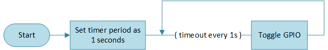
Timer Timeout Diagram
Users can modify pin information, output frequency, and whether to dynamically change the frequency through different macro configurations. For specific macro configurations, refer to Configurations.
Requirements
For requirements, please refer to the Requirements.
Wiring
Connect P0_0 and LED0.
The LED driver circuit is shown below.
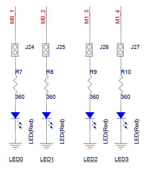
LED Driver Circuit Diagram
Configurations
-
The following macro can be configured to modify the pin definition.
#define OUTPUT_PIN          P0_0
#define GPIO_PIN            GPIO_GetPin(OUTPUT_PIN)
#define GPIO_PORT           GPIO_GetPort(OUTPUT_PIN)
-
The following macro can be configured to modify the timing.
#define TIME_UINT            40                            /*< 40M source clock is divided to get unit: 1us */
#define TIME_TIMING          1000000                       /*< Set this macro to 1000000, with a timer duration of 1s. The unit for this macro is in microseconds (us). */
#define TIMER_PERIOD         (TIME_TIMING * TIME_UINT - 1)
Building and Downloading
For building and downloading, please refer to the Building and Downloading.
Experimental Verification
-
When the EVB starts, observe the following log within the Debug Analyzer.
Start timer interrupt test!
After enabling TIM, each time the count reaches 1 second, a TIM interrupt will be triggered. Within the interrupt function, the output level of P0_0 is toggled, allowing LED0 to be observed flashing once every second.
Code Overview
This section mainly introduces the code and process description for initialization and corresponding function implementation in the sample.
Source Code Directory
The directory for project file and source code are as follows:
Project directory:
sdk\samples\peripheral\timer\timer_interrupt\projSource code directory:
sdk\samples\peripheral\timer\timer_interrupt\src
Initialization
The initialization flow for peripherals can refer to Initialization Flow in General Introduction.
-
Call
Pad_Config()andPinmux_Config()to configure the PAD and PINMUX of the corresponding pins.void board_gpio_init(void) { Pad_Config(OUTPUT_PIN, PAD_PINMUX_MODE, PAD_IS_PWRON, PAD_PULL_NONE, PAD_OUT_ENABLE, PAD_OUT_HIGH); Pinmux_Config(OUTPUT_PIN, DWGPIO); }
Call
RCC_PeriphClockCmd()to enable the GPIO clock.-
Initialize the GPIO peripheral:
Define the
GPIO_InitTypeDeftypeGPIO_InitStruct, and callGPIO_StructInit()to pre-fillGPIO_InitStructwith default values.Modify the
GPIO_InitStructparameters as needed. The initialization parameter configurations for GPIO are shown in the table below. CallGPIO_Init()to initialize the GPIO peripheral.
GPIO Hardware Parameters |
Setting in the |
GPIO |
|---|---|---|
GPIO pin |
|
|
GPIO direction |
Call
RCC_PeriphClockCmd()to enable the TIM clock.-
Initialize the TIM peripheral:
Define the
TIM_TimeBaseInitTypeDeftypeTIM_InitStruct, and callTIM_StructInit()to pre-fillTIM_InitStructwith default values.Modify the
TIM_InitStructparameters as needed. The initialization parameter configurations for TIM are shown in the table below. CallTIM_TimeBaseInit()to initialize the TIM peripheral.Call
NVIC_Init()to configure the NVIC. For NVIC-related configurations, refer to Interrupt Configuration.Call
TIM_ClearINT()andTIM_INTConfig()to clear the TIM interrupt and enable the TIM interrupt.
TIM Hardware Parameters |
Setting in the |
TIM |
|---|---|---|
Counter mode |
||
PWM mode |
||
Count value |
|
Call
TIM_Cmd()to enable the TIM peripheral.
Functional Implementation
After enabling the TIM peripheral, the TIM begins timing. When the timing period ends, an interrupt is triggered, entering the interrupt handler function Timer2_Handler.
When the timer of TIM2 reaches the specified timing, it triggers an interrupt and enters the interrupt handling function called Timer2_Handler.
Clear the interrupt flag of TIM2 and disable TIM2.
Determine the current LED status and call
GPIO_WriteBit()to toggle the output level of P0_0.Enable TIM2 again.
void TIMER_Handler(void)
{
    TIM_ClearINT(TIMER_NUM);
    TIM_Cmd(TIMER_NUM, DISABLE);
    if (!LED_Status)
    {
        GPIO_WriteBit(GPIO_PORT, GPIO_PIN, (BitAction)(1));
        LED_Status = 1;
    }
    else
    {
        GPIO_WriteBit(GPIO_PORT, GPIO_PIN, (BitAction)(0));
        LED_Status = 0;
    }
    //Add user code here
    TIM_Cmd(TIMER_NUM, ENABLE);
}
See Also
Please refer to the relevant API Reference: