ADC Continuous Mode
This sample code guide is designed to help users easily and comprehensively understand ADC sample. This sample demonstrates how ADC samples data in continuous mode with charger and discharger enabled. This sample uses continuous mode of the ADC peripheral to measure voltage on P0_0 with charger and discharger enabled.
Requirements
For hardware requirements, please refer to the Requirements.
Wiring
Connect P0_0 of EVB to an external DC voltage source. Input voltage of P0_0 must range from 0 to 3.3V.
Configurations
-
The following macros can be configured to modify the sampling interval.
#define ADC_TIMER_PERIOD 2000
-
The entry function is as follows, call this function in
main()to run this sample code. For more details, please refer to the Initialization.adc_continuous_mode_demo();
Building and Downloading
For building and downloading, please refer to the Building and Downloading.
Experimental Verification
-
Disconnect VADP and 5V of EVB, press the Reset button on the EVB. After initialization is complete, the ADC begins sampling. Once ADC sampling is finished, the raw data collected and the converted voltage values will be printed in Debug Analyzer.
adc_dma_handler: adc_dma_buffer[xxx] xxx, result[xxx] xxx
...
Connect VADP and 5V of EVB, ADC stops continuous sampling and the charger is enabled.
-
Disconnect VADP and 5V of EVB, ADC starts continuous sampling and prints the raw data collected and the converted voltage values in Debug Analyzer.
adc_dma_handler: adc_dma_buffer[xxx] xxx, result[xxx] xxx
...
Code Overview
This section introduces the code and process description for initialization and corresponding function implementation in the sample.
Note
To use the mode, please turn off Charger auto enable and Battery detection support on the MCUConfig Tool. As shown in Turn Off Charger on the MCUConfig Tool.
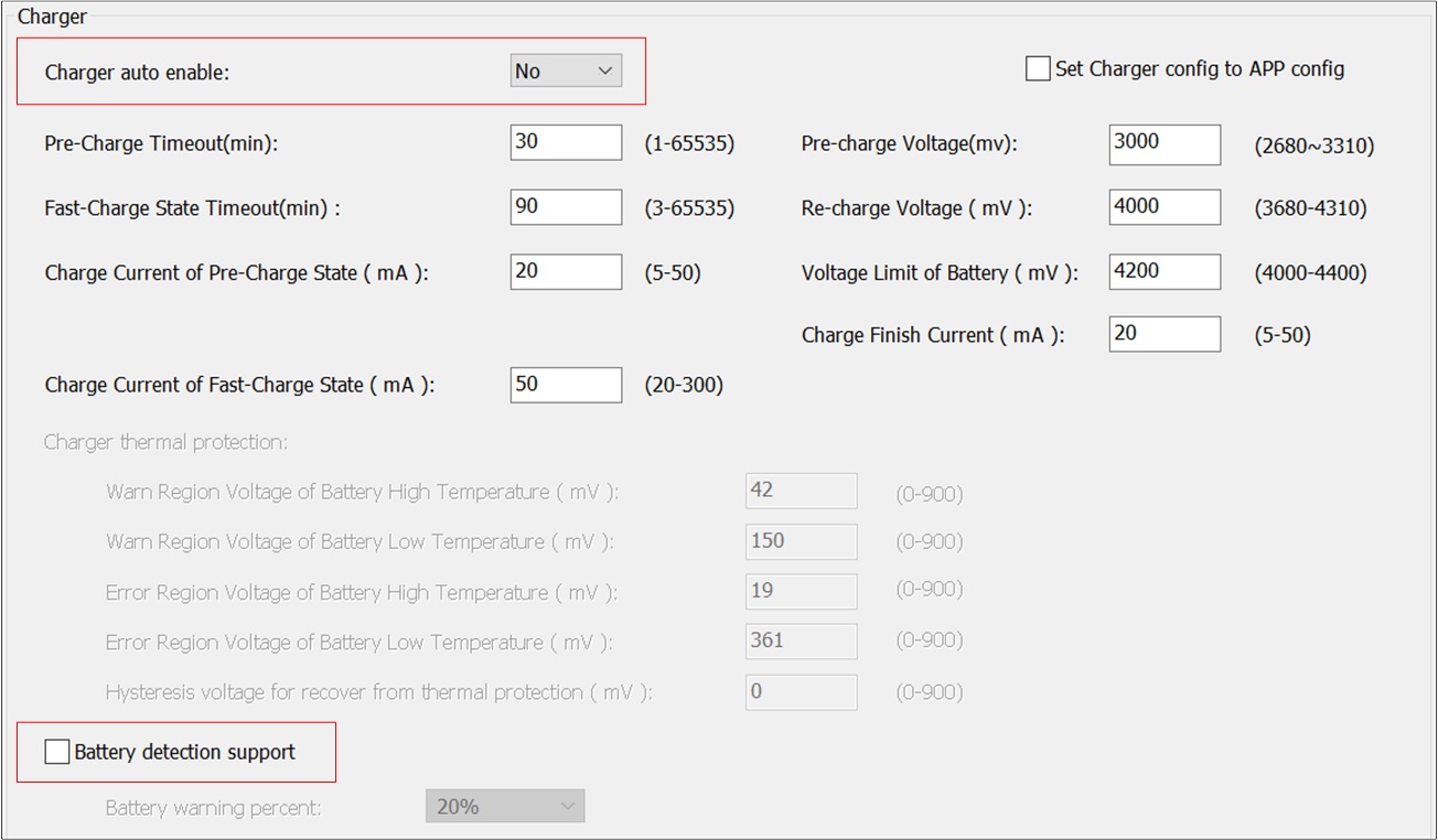
Turn Off Charger on the MCUConfig Tool
Source Code Directory
For project directory, please refer to Source Code Directory.
Source code directory:
sdk\src\sample\io_demo\adc\adc_continuous_mode\adc_continuous_mode_demo.c.
ADC Initialization
The initialization flow for peripherals can refer to Initialization Flow.
ADC continuous mode initialization flow is shown in the following figure.
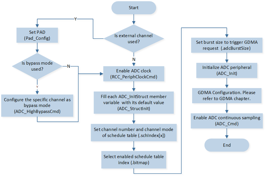
ADC Continuous Mode Initialization Flow Chart
Call
adp_register_state_change_cb()to register ADP 5V callback.Call
os_timer_createto create a software timer.-
Call
Pad_Config()andPinmux_Config()to initialize the pin.static void board_adc_init(void) { Pad_Config(ADC_0, PAD_SW_MODE, PAD_IS_PWRON, PAD_PULL_NONE, PAD_OUT_DISABLE, PAD_OUT_LOW); Pinmux_Config(ADC_0, IDLE_MODE); }
Call
RCC_PeriphClockCmd()to enable the ADC clock and function.-
Initialize the ADC peripheral:
Define the
ADC_InitTypeDeftypeadc_init_struct, and callADC_StructInitto pre-filladc_init_structwith default values.Modify the
adc_init_structparameters as needed. The ADC initialization parameter configuration is shown in the table below.Call
ADC_Initto initialize the ADC peripheral.
ADC Initialization Parameters ADC Hardware Parameters
Setting in the
adc_init_structVariablesADC
Bit Map
0x01
Schedule Index
Index 0 is set to
EXT_SINGLE_ENDED(0).Burst Size
8
Call
ADC_INTConfig()to enable ADC FIFO read error interruptADC_INT_FIFO_RD_ERR.Call
NVIC_Initto enable NVIC of ADC.
GDMA Initialization
GDMA initialization flow is shown in the following figure.
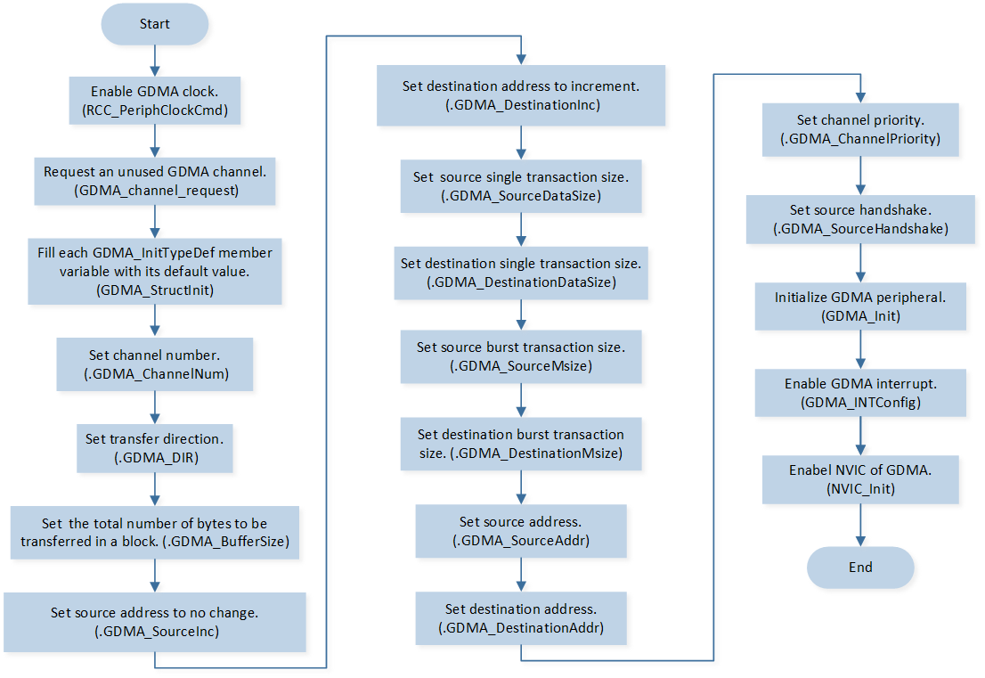
GDMA Initialization Flow Chart
Call
RCC_PeriphClockCmd()to enable the GDMA clock and function.Call
GDMA_channel_requestto request an unused GDMA channel.-
Initialize the GDMA peripheral:
Define the
GDMA_InitTypeDeftypeGDMA_InitStruct, and callGDMA_StructInit()to pre-fillGDMA_InitStructwith default values.Modify the
GDMA_InitStructparameters as needed. The GDMA initialization parameter configuration is shown in the table below.Call
GDMA_Initto initialize the GDMA peripheral.
GDMA Initialization Parameters GDMA Hardware Parameters
Setting in the
GDMA_InitStructVariablesGDMA
Channel Num
ADC_DMA_CHANNEL_NUMTransfer Direction
Buffer Size
80
Source Address Increment or Fix
Destination Address Increment or Fix
Source Data Size
Destination Data Size
Source Burst Transaction Length
Destination Burst Transaction Length
Source Address
(uint32_t)(&(ADC->FIFO))Destination Address
(uint32_t)(&adc_dma_buffer[0])Source Handshake
Call
GDMA_INTConfig()to enable GDMA transfer complete interruptGDMA_INT_Transfer.Call
NVIC_Initto enable NVIC of GDMA.
Functional Implementation
Enable ADC Contiunous Sampling
ADP 5V Callback Handle
-
If ADP plug in:
-
Deinitialize ADC peripheral:
Call
os_timer_stopto stop software timer.Call
os_timer_stopto delete software timer.Call
RCC_PeriphClockCmd()to disable the ADC clock and function.Call
Pinmux_Deinit()to deinitialize the pin.Call
NVIC_Initto disable NVIC of ADC.Call
GDMA_Cmdto disable GDMA.Call
GDMA_channel_release()to release GDMA channel used by ADC continuous mode.
Call
adc_mgr_initto initialize ADC manager module.Call
charger_api_enable_chargerto enable charger.
-
-
If ADP plug out:
Call
charger_api_disable_chargerto disable charger.Call
adc_mgr_deinit()to close ADC manager module.Initialize software timer and ADC and GDMA, please refer to steps 2 to 14 of Source Code Directory.
ADC Interrupt Handle
When read the empty FIFO, ADC FIFO read error interrupt is triggered:
Call
ADC_GetIntFlagStatus()to checkADC_INT_FIFO_RD_ERRinterrupt status flag.Call
ADC_ClearINTPendingBit()to clearADC_INT_FIFO_RD_ERRinterrupt.
GDMA Interrupt Handle
When GDMA transfer is completed, transfer complete interrupt is triggered:
Call
GDMA_ClearINTPendingBit()to clearGDMA_INT_Transferinterrupt.Call
ADC_Cmdto disable ADC.Call
GDMA_GetTransferLen()to get GDMA transfer data length.Call
ADC_GetResto get conversion result.Call
ADC_ClearFifo()to clear ADC FIFO.Call
os_timer_startto start software timer.
Software Timer Callback Handle
When the software timer expires, the software timer callback function will be executed:
Call
GDMA_SetDestinationAddress()to set GDMA transmission destination address.Call
GDMA_Cmdto enable GDMA.Call
ADC_Cmdto enable ADC contiunous sampling.