GPIO Latch
This example uses ENHTIM to implement the counter latching function during external signal changes
Configure the P2_4 pin as a GPIO output pin to simulate external signal changes, with the level continuously toggling. Set the P2_2 pin as the input for ENHTIM to detect changes in the external signal.
Connect the P2_2 pin to the P2_4 pin. When P2_2 detects a rising edge in the signal, ENHTIM triggers a latch count. After accumulating three trigger latch counts,
the ENHTIM_INT_LATCH_CNT_FIFO_THD interrupt is triggered, executing the user application program within the interrupt function.
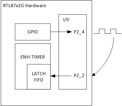
Latch GPIO Diagram
Users can modify pin information, output frequency, and whether to dynamically change the frequency through different macro configurations. For specific macro configurations, refer to Configurations.
Requirements
For requirements, please refer to the Requirements.
Wiring
Connect P2_4 to P2_2.
Configurations
-
The following macro can be configured to modify the output pin of the GPIO.
#define OUTPUT_PIN          P2_4
#define GPIO_PIN            GPIO_GetPin(OUTPUT_PIN)
#define GPIO_PORT           GPIO_GetPort(OUTPUT_PIN)
-
The following macros can be configured to modify the count trigger pins of ENHTIM.
#define INPUT_PIN P2_2
Building and Downloading
For building and downloading, please refer to the Building and Downloading.
Experimental Verification
-
When the EVB starts, observe the following log within the Debug Analyzer.
Start latch_gpio test!
-
After initialization, P2_4 will continuously toggle. Each time P2_2 detects a rising edge, it records the current counter value. Once P2_2 detects a total of three rising edges, the
ENHTIM_INT_LATCH_CNT_FIFO_THDinterrupt is triggered. Within the interrupt function, the counter values at the three trigger latches will be retrieved and printed.ENH_TIM0 ENHTIM_INT_LATCH_CNT2_FIFO_THD ENH_TIM0 fifo length = 3 ENH_TIM0 data[0] = xxx ENH_TIM0 data[1] = xxx ENH_TIM0 data[2] = xxx ENH_TIM0 ENHTIM_INT_LATCH_CNT2_FIFO_THD ...
As P2_4 continues to toggle, the
ENHTIM_INT_LATCH_CNT_FIFO_THDinterrupt will keep triggering, continuously printing logs.
Code Overview
This section mainly introduces the code and process description for initialization and corresponding function implementation in the example.
Source Code Directory
The directory for project file and source code are as follows:
Project directory:
sdk\samples\peripheral\enhtimer\latch_gpio\projSource code directory:
sdk\samples\peripheral\enhtimer\latch_gpio\src
Initialization
The initialization flow for peripherals can refer to Initialization Flow in General Introduction.
-
Call
Pad_Config()andPinmux_Config()to configure the PAD and PINMUX of the corresponding pins.void board_gpio_init(void) { Pad_Config(OUTPUT_PIN, PAD_PINMUX_MODE, PAD_IS_PWRON, PAD_PULL_NONE, PAD_OUT_ENABLE, PAD_OUT_HIGH); Pinmux_Config(OUTPUT_PIN, DWGPIO); }
Call
RCC_PeriphClockCmd()to enable the GPIO clock.-
Initialize the GPIO peripheral:
Define the
GPIO_InitTypeDeftypeGPIO_InitStruct, and callGPIO_StructInit()to pre-fillGPIO_InitStructwith default values.Modify the
GPIO_InitStructparameters as needed. The initialization parameter configurations for GPIO are shown in the table below. CallGPIO_Init()to initialize the GPIO peripheral.
GPIO Hardware Parameters |
Setting in the |
GPIO |
|---|---|---|
GPIO pin |
|
|
GPIO direction |
Call
RCC_PeriphClockCmd()to enable the ENHTIM clock.-
Initialize the ENHTIM peripheral:
Define the
ENHTIM_InitTypeDeftypeENHTIM_InitStruct, and callENHTIM_StructInit()to pre-fillENHTIM_InitStructwith default values.Modify the
ENHTIM_InitStructparameters as needed. The initialization parameter configurations for ENHTIM are shown in the table below. CallENHTIM_Init()to initialize the ENHTIM peripheral.
ENHTIM Hardware Parameters |
Setting in the |
ENHTIM |
|---|---|---|
Counter mode |
||
Latch count function |
||
Counter latch trigger mode |
||
Latch counter fifo threshold |
3 |
|
Latch trigger pin |
|
Call
NVIC_Init()to configure the NVIC. For NVIC-related configurations, refer to Interrupt Configuration.-
Call
ENHTIM_ClearINTPendingBit()andENHTIM_INTConfig()to clear the ENHTIM interrupt and enable the ENHTIM interrupt.ENHTIM_ClearINTPendingBit(ENHTIMER_NUM, ENHTIM_INT_LATCH_CNT_FIFO_FULL); ENHTIM_INTConfig(ENHTIMER_NUM, ENHTIM_INT_LATCH_CNT_FIFO_FULL, ENABLE); ENHTIM_ClearINTPendingBit(ENHTIMER_NUM, ENHTIM_INT_LATCH_CNT_FIFO_THD); ENHTIM_INTConfig(ENHTIMER_NUM, ENHTIM_INT_LATCH_CNT_FIFO_THD, ENABLE);
Call
ENHTIM_Cmd()to enable the ENHTIM peripheral.
Functional Implementation
The diagram below illustrates the ENHTIM Latch function flow.
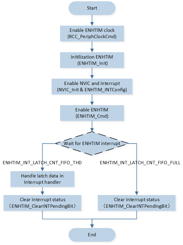
ENHTIM Latch flow
When the trigger pin configured by ENHTIM detects that the number of rising edge triggers reaches the FIFO set threshold, it triggers the ENHTIM_INT_LATCH_CNT_FIFO_THD interrupt, entering the interrupt handler function Enhanced_Timer0_Handler.
If the threshold is set too high, data in the FIFO may not be moved out in time, triggering the ENHTIM_INT_LATCH_CNT_FIFO_FULL interrupt.
-
Trigger FIFO threshold interrupt
Check if the interrupt status bit is
ENHTIM_INT_LATCH_CNT_FIFO_THD, disable the interrupt.Call
ENHTIM_GetLatchCountFIFOLength()to get the number of data in the FIFO.Call
ENHTIM_ReadLatchCountFIFO()to get the count value and print the value data.Clear the interrupt flag and enable the interrupt.
-
Trigger FIFO Full Interrupt
Determine whether the interrupt status bit is
ENHTIM_INT_LATCH_CNT_FIFO_FULL.Clear the interrupt flag bit.
void Enhanced_Timer0_Handler()
{
    ...
    if (ENHTIM_GetINTStatus(ENH_TIM0, ENHTIM_INT_LATCH_CNT_FIFO_FULL))
    {
        APP_PRINT_INFO0("ENH_TIM0 ENHTIM_INT_LATCH_CNT2_FIFO_FULL\r\n");
        ENHTIM_ClearINTPendingBit(ENH_TIM0, ENHTIM_INT_LATCH_CNT_FIFO_FULL);
    }
    if (ENHTIM_GetINTStatus(ENH_TIM0, ENHTIM_INT_LATCH_CNT_FIFO_THD))
    {
        APP_PRINT_INFO0("ENH_TIM0 ENHTIM_INT_LATCH_CNT2_FIFO_THD\r\n");
        ENHTIM_INTConfig(ENHTIMER_NUM, ENHTIM_INT_LATCH_CNT_FIFO_THD, DISABLE);
        uint8_t length = ENHTIM_GetLatchCountFIFOLength(ENH_TIM0);
        uint32_t data[4] = {0};
        ENHTIM_ReadLatchCountFIFO(ENH_TIM0, data, length);
        /* Only for debugging, removed in actual application. */
        APP_PRINT_INFO1("ENH_TIM0 fifo length = %d\r\n", length);
        for (uint8_t i = 0; i < length; i++)
        {
            /* Only for debugging, removed in actual application. */
            APP_PRINT_INFO2("ENH_TIM0 data[%d] = 0x%x\r\n", i, data[i]);
        }

        ENHTIM_ClearINTPendingBit(ENH_TIM0, ENHTIM_INT_LATCH_CNT_FIFO_THD);
        ENHTIM_INTConfig(ENH_TIM0, ENHTIM_INT_LATCH_CNT_FIFO_THD, ENABLE);
    }
}
See Also
Please refer to the relevant API Reference: