Audio Line
The purpose of this document is to introduce the concept and functionalities of Audio Line, its implementation features, as well as the operating principle between the Audio Line and the application layer.
The Audio Line is a high-level function module of the Audio Subsystem, which provides a set of dedicated high-level APIs for stream loopback. The key distinction between the Audio Line and the Audio Track is that the Audio Line stream bypasses the application layer and performs direct underlying stream loopback.
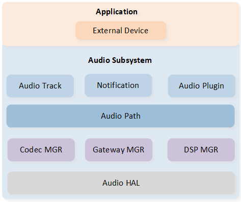
Audio Subsystem Architecture
Overview
The figure below provides an overview of how the Audio Line operates across different modules. Each instance of Audio Line takes the dedicated stream from local input Peripherals and pours it into local output Peripherals. The local input Peripheral can include builtin MIC, external MIC, AUX-In, or SPDIF-In, while the local output Peripheral can include builtin SPK, external SPK, AUX-Out, or SPDIF-Out. The Audio Line supports flexible combinations of the input and output Peripherals.
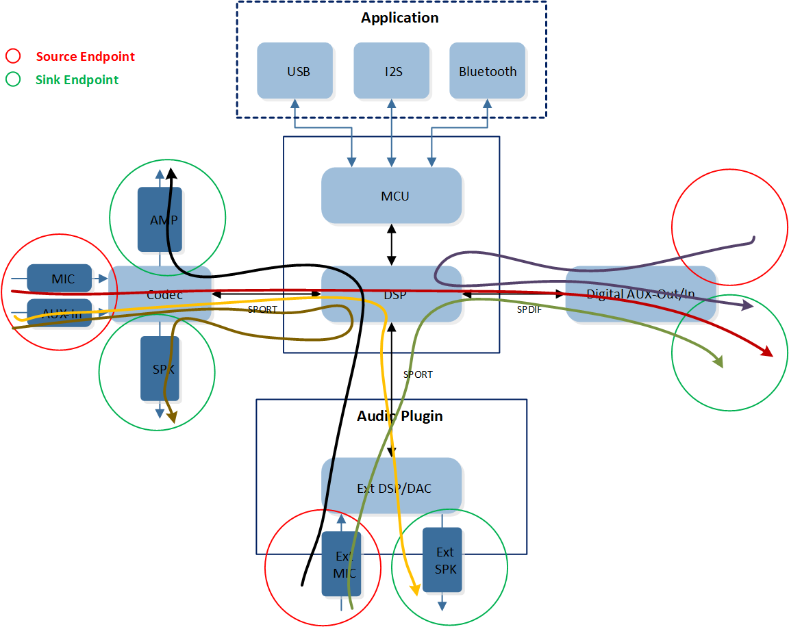
Audio Line Overview
The table below lists current supported combination of Endpoints of Audio Line.
Endpoint in |
Endpoint out |
|---|---|
MIC |
SPK |
MIC |
SPDIF |
AUX |
SPK |
AUX |
SPDIF |
SPDIF |
MIC |
SPDIF |
SPDIF |
Implementation
The implementation module of Audio Line is mainly used to introduce the Audio Line modeling, Audio Line lifecycle, Audio Route configuration, and the detailed process of the DSP.
Line Modeling
The Audio Line is designed to be based on the Audio Path component. As shown in the figure below, the Audio Line utilizes the capabilities of the Audio Path component to configure and control the hardware routing. As a result, the state of the Audio Line is synchronized with the state of the Audio Path component.
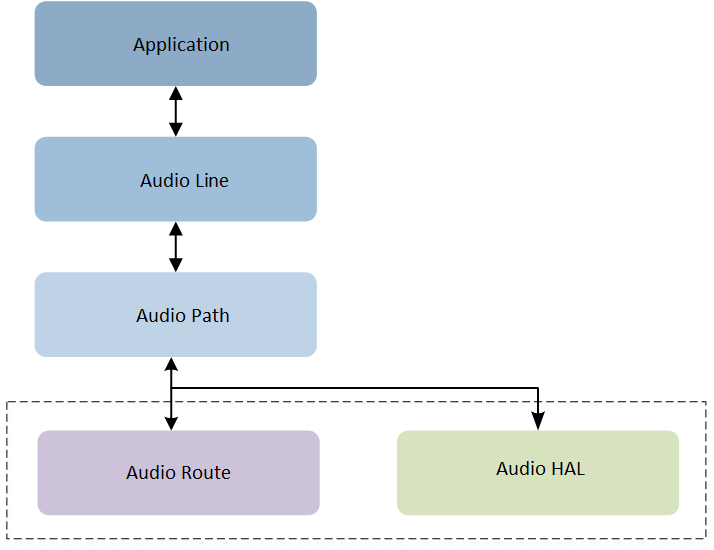
Audio Line Modeling
Line Lifecycle
Each instance of Audio Line follows a specific lifecycle defined by the following states: Released, Creating, Created, Starting, Started, Stopping, Stopped, Pausing, Paused, and Releasing. The state transition of each Audio Line instance should follow this lifecycle diagram, with the initial state being Released. Then the Audio Line instance enters the Creating state and waits for the completion of the create action before transitioning to the Created state. Afterwards, the application can choose to release or start this Audio Line instance. Similarly, an active Audio Line instance can be stopped on demand by transitioning from the Stopping state to the Stopped state. Finally, the Audio Line instance is released, transitioning from the Releasing state back to the Released state.
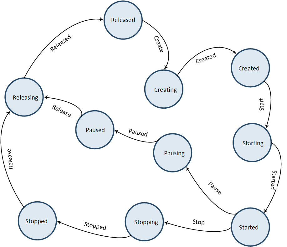
Audio Line Lifecycle
Audio Route Configuration
The following diagram shows the configuration of the Audio Route with a 2-channel RX input and a 2-channel TX output. Audio Line can support three different types of Endpoints: MIC, AUX, and SPDIF. The application can configure the corresponding Endpoint based on actual needs. All Endpoints can be selected in the MCUConfig Tool, and ultimately, the logical IO actually enabled depends on the device specified when the application creates the Audio Line instance.
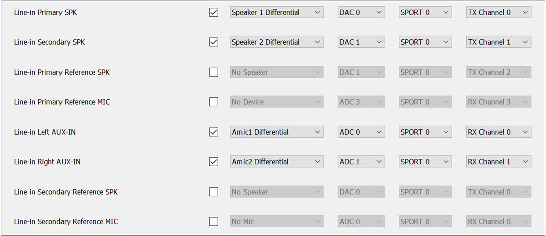
Audio Route Configuration
Note
For RTL87x3E EVB, due to hardware limitations, the pins for AUX-L, AUX-R, and MIC2 are shared. Therefore, when dealing with a Line mix scenario, we must ensure that different MICs are configured. For example, in Line mix Record scenario, if the Endpoint selected for the Audio Line is AUX, then MIC2 cannot be selected when configuring the MIC for recording.
DSP Module Process
For this section, we will use the above configuration as an example to introduce the implementation of Audio Line within the DSP.
Firstly, the DSP transfers TDM formatted data from the SPORT RX DMA. Here, the SPORT is configured as TDM4 in the MCUConfig Tool, so the DSP receives 4-channel data. Currently, the DSP supports three TDM modes: TDM2, TDM4, and TDM6.
Secondly, the Scatter module splits the 4-channel data into four substreams and also performs some gain adjustment and resampling actions.
The Reorder module primarily selects the corresponding channels for processing based on the configuration of Audio Line in the Audio Route. In this case, two Gateway RX channels have been configured, so after being processed by the Reorder module, two of the four sub streams retain the data from the configured RX channels.
The Signal Process module mainly handles certain algorithms, such as audio EQ functionality. For the Audio Line, there are currently no special algorithm processes implemented within the DSP.
The Mixer module also performs some gain adjustment and resampling actions.
-
Finally, the data signals are processed by the Gateway Process module and output in the TX direction. Currently, DSP only supports TDM2 in the TX direction.
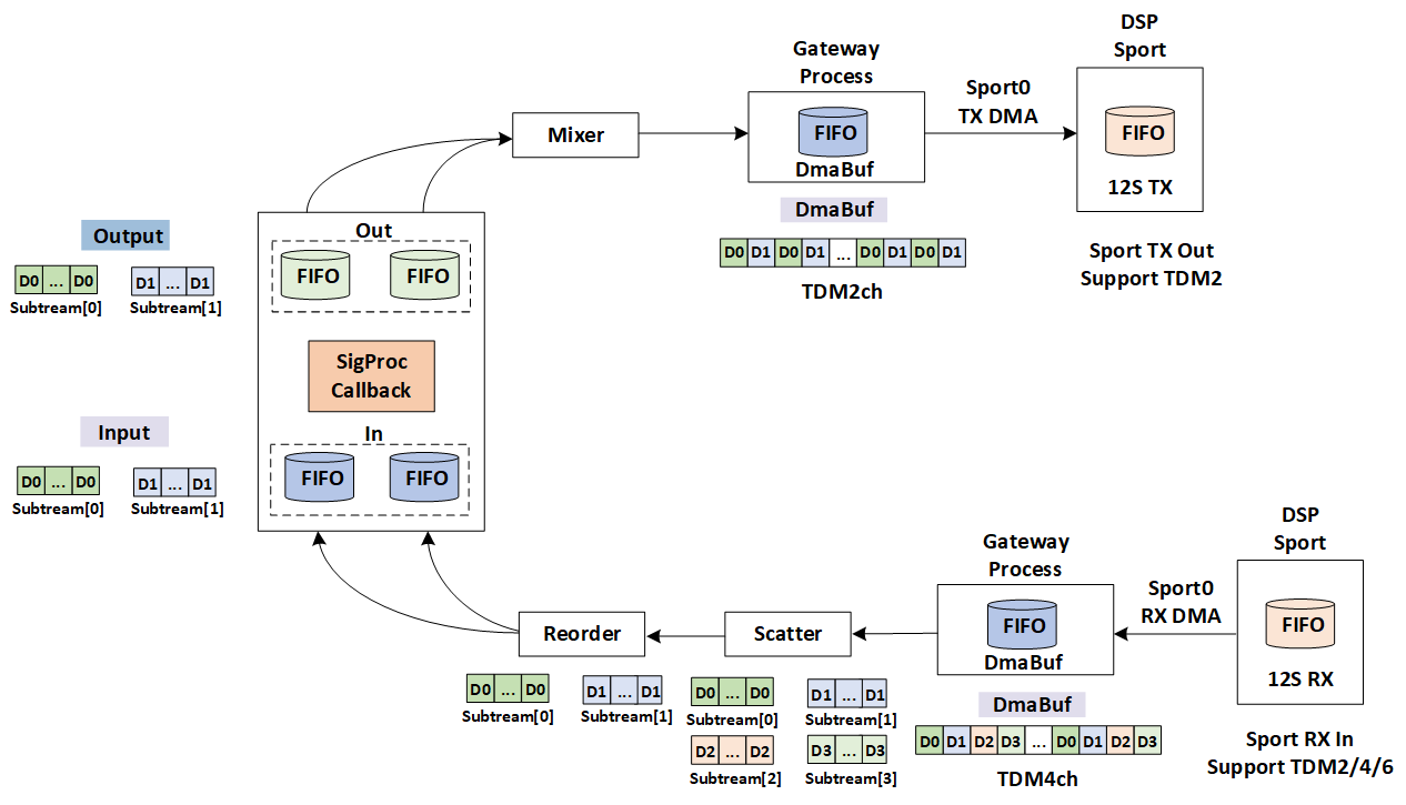
Audio Line DSP Module Process
Note
Let's explain why both the Scatter and Mixer modules handle gain and resampling. Using the Signal Process module for voice handling as an example, the DSP can only process voice data at 16kHz or 32kHz. However, the RX data is configured according to the SPORT setting, which may not be at 16kHz or 32kHz. Therefore, the Scatter module must first perform resampling. Once this is done, the Signal Process module carries out the algorithm processing. Finally, the sample rate for TX output also depends on the SPORT configuration, which may necessitate another resampling by the Mixer module.
Operating Principle
The operating principle of application mainly describes the detailed interaction flow between Audio
Line and application. The application calls line_in_create() to create an Audio Line instance.
After creating the Audio Line, the application can call the line_in_start() to start the
Audio Line instance. After that, the underlying stream loopback can be performed. Similarly, once
the stream loopback is completed, the application calls the line_in_stop() interface to
stop the Audio Line instance. Finally, the Audio Line instance can be released through the
line_in_destroy() interface.
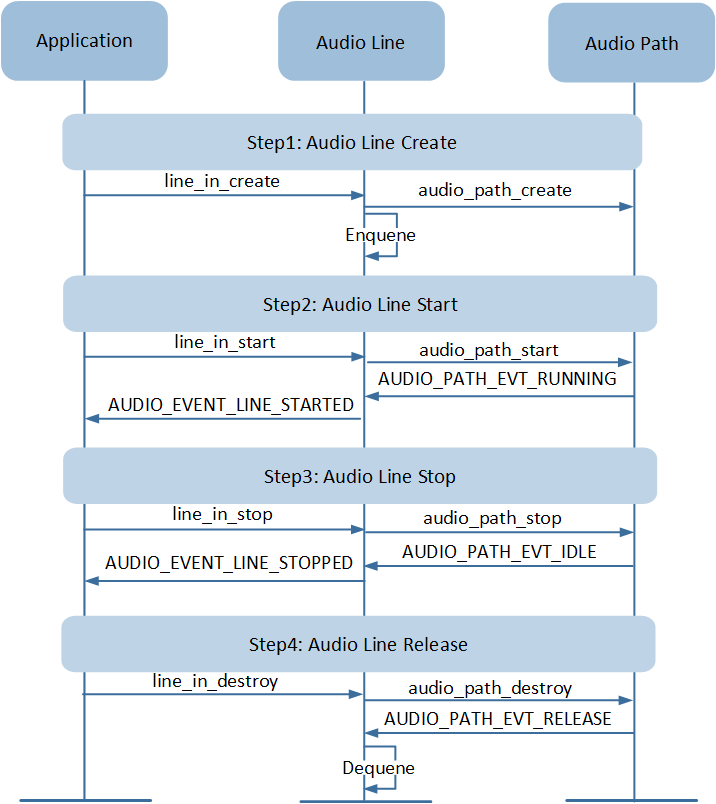
Application Line Flow
API Usage
Below are the application programming interfaces provided by the Audio Line component, along with a brief introduction and precautions for their usage.
-
To create an Audio Line instance for stream loopback, the following parameters need to be set correctly. The device can refer to Audio Device Bitmask. The supported sample rate input and sample rate output are 48kHz and 96kHz. The APIs of Audio Line action are shown below:
bool line_in_create(uint32_t device,
                    uint32_t sample_rate);

bool line_in_start(void);

bool line_in_stop(void);

bool line_in_destroy(void);
-
Audio Line also provides the following APIs for strength monitoring of signal output or signal input.
refresh_intervalmeans refresh interval in milliseconds for signal level.bool line_in_signal_out_monitoring_start(uint16_t refresh_interval); bool line_in_signal_out_monitoring_stop(void); bool line_in_signal_in_monitoring_start(uint16_t refresh_interval); bool line_in_signal_in_monitoring_stop(void);
See Also
Please refer to the relevant API Reference: