One Wire
This document introduces the implementation and operational details of One Wire UART for communication between microprocessors using a single wire connection. It includes an explanation of the required electrical interface, UART configuration, and timing requirements for this communication method. Also, it introduces the power line communication methods, describes the way to use the ADPIN pin for One Wire communication.
Additionally, it provides an overview of the One Wire API and demonstrates the One Wire UART firmware implementation.
One Wire UART
One Wire UART works in half-duplex mode. Both devices connected to the single wire line are capable of changing the state of the line. The state of the line can either be high or low.
When there are no devices communicating, this line will be in an idle state and in pull-high mode. When one of the devices wants to send data, it can pull the line low. As both devices are on the same line, the transmitted data will be received back. The upper layer protocol will control the timing of transmission and reception.
One Wire Timing and Diagram
One Wire UART uses the open-drain output method, and the final waveform is the result of the TX lines on both sides of the device. The specific diagram is shown in the figure below:
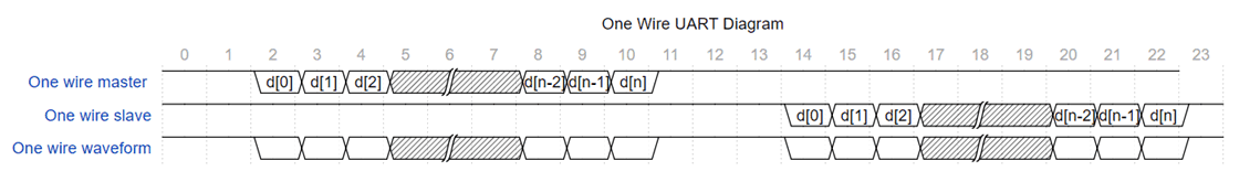
One Wire UART Diagram
One Wire Working in ADPIN Pin
It is supported for ADPIN pin to be set to One Wire UART mode. So that the system can be charged and data transmitted through the one pin.
One Wire for ADPIN Introduction
The RTL87x3D and RTL87x3E support One Wire UART over the ADPIN pin. The ADPIN pin can be set to the digital pinmux mode. It can be set to UART mode, which can transmit and receive data over the ADPIN pin.
Communication and charging functions are time-division multiplexed. When the ADPIN is used for One Wire UART mode, the charger function will be disabled. Users can use the ADPIN pin for both power supply and communication.
The timing diagram of charging and communication is shown in the figure below:

One Wire Waveform
When the input level exceeds the power level required for charging, the One Wire UART communication is disconnected, and the charging function is turned on. The level threshold for charging can be set using the MCUConfig Tool.
When the input voltage of the ADPIN pin is 3.3V, the system will receive 5V out and IO in events. The firmware will turn off charging and enable One Wire UART communication.
When the ADPIN 5V and IO are detected at the ground, the system will assume that the current One Wire UART and charger are disconnected.
The Limitation of ADPIN One Wire
Because the ADPIN needs to be used for power supply and communication functions, the capacitance attached to the ADPIN will affect the baud rate that One Wire UART can support. The baud rate limitation is shown as below:
When the capacitance is 100pF, the maximum baud rate is 1000000.
When the capacitance is 1nF, the maximum baud rate is 115200.
Note
RTL87x3D and RTL87x3E support ADPIN pin for general IO usage. RTL87x3EP does not support ADPIN pin as general IO.
One Wire API Overview
Except the following APIs are required to configure the UART, other APIs are consistent with the dual-line UART.
extern void UART_OneWireConfig(UART_TypeDef *UARTx, bool is_enable);
Using the ADPIN pin as a UART, one can use the following ADPIN-related APIs. Register the 5V or IO changes callback.
bool adp_register_state_change_cb(T_ADP_DETECT adp_type, P_ADP_PLUG_CBACK cback, void *user_data);
Get the current ADPIN state.
T_ADP_STATE adp_get_current_state(T_ADP_DETECT adp_type);
To disable receiving data when switched to transmission mode, users can call the following API.
// disable UART RX interrupt
UART_INTConfig(UART0, UART_INT_RD_AVA | UART_INT_IDLE | UART_INT_LINE_STS, DISABLE);
And switch back to RX mode when transmission is done.
// clear Rx FIFO
UART_ClearRxFifo(UART0);
// enable UART RX interrupt
UART_INTConfig(UART0, UART_INT_RD_AVA | UART_INT_IDLE | UART_INT_LINE_STS, ENABLE);
Tool Configuration of One Wire
To use the HAL ADP API to obtain ADPIN information, select ADPIN-related options in advance.
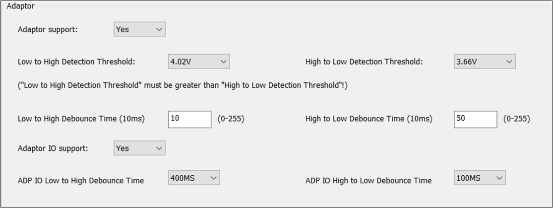
ADPIN Configure
See Also
Please refer to the relevant API Reference: