Audio Pipe
The purpose of this document is to introduce the concept and functionalities of Audio Pipe, its implementation features, as well as the operating principle between the Audio Pipe and the application layer.
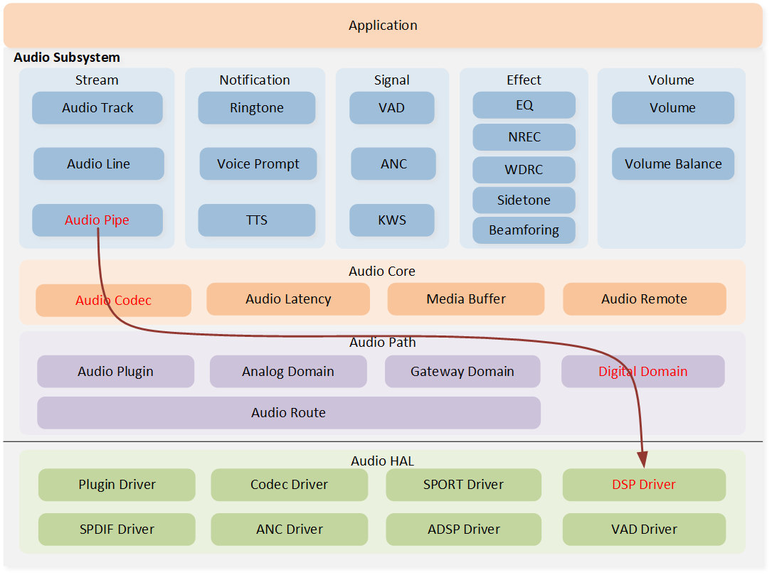
The Audio Pipe is a high-level function module of the Audio Subsystem, which provides a process for codec format conversion. This means that an input data stream in one codec format will be processed and converted into an output data stream in another codec format. For Audio Pipe, the main routing is the flow of the red arrows shown in the diagram. Since the Audio Pipe does not involve any Audio Route configurations, it bypasses the process of Audio Route.
Audio Subsystem Architecture
Overview
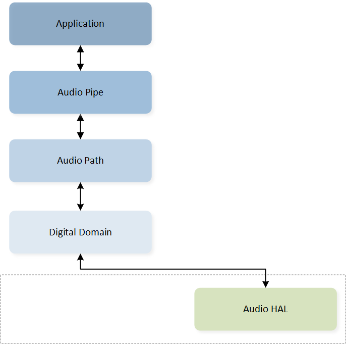
The following diagram provides a simple description of how the Audio Pipe operates between different modules. The application layer inputs the data stream that requires encoding format conversion from the source endpoint. After undergoing DSPs processing and conversion, the data is then delivered back to the application layer.

Audio Pipe Overview
By establishing an abstract codec Audio Pipe model, the input data stream in one codec format will be processed and converted into an output data stream in another codec format. It is important to note that the Audio Pipe not only facilitates the conversion between different codec types but also enables the conversion of specific codec attributes within the same codec type, allowing the application to configure it according to specific requirements. Additionally, this transformation method can also be cascaded, meaning the data stream output from the sink endpoint of one Pipe can serve as the input data stream for the source endpoint of the next Pipe.

Codec Pipe Overview
The table below lists the codec types supported by the Audio Pipe.
Type |
Value |
|---|---|
|
0x00 |
|
0x01 |
|
0x02 |
|
0x03 |
|
0x04 |
|
0x05 |
|
0x06 |
|
0x07 |
|
0x08 |
|
0x09 |
|
0x0A |
|
0x0B |
|
0x0C |
Implementation
The implementation module of Audio Pipe is mainly used to introduce the Audio Pipe modeling, Audio Pipe lifecycle, and the detailed process of the DSP module.
Pipe Modeling
The design of the Audio Pipe is based on the Audio Path and controlled by the Audio Path to configure the digital domain and underlying hardware settings.
Audio Pipe Modeling
Note
The Audio Pipe only controls Audio Path's Digital Domain, so the Audio Route is not included in the Audio Pipe's control.
Pipe Lifecycle
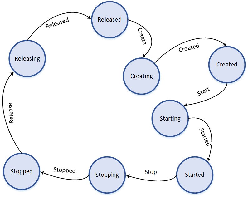
Each instance of Audio Pipe follows a specific lifecycle defined by the following states: Released, Creating, Created, Starting, Started, Stopping, Stopped, and Releasing. The state transition of each Audio Pipe instance should follow this lifecycle diagram, with the initial state being Released. Then the Audio Pipe instance enters the Creating state and waits for the completion of the create action before transitioning to the Created state. Afterwards, the application can choose to release or start this Audio Pipe instance. Similarly, an active Audio Pipe instance can be stopped on demand by transitioning from the Stopping state to the Stopped state. Finally, the Audio Pipe instance is released, transitioning from the Releasing state back to the Released state.
Audio Pipe Lifecycle
DSP Module Process
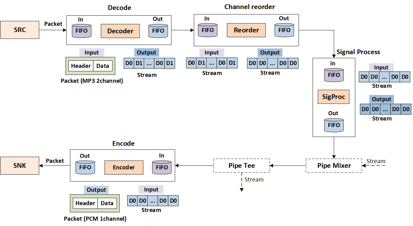
We specifically introduce the process of Audio Pipe data stream conversion, taking the example of converting 2-channel MP3 data to 1-channel PCM data.
The application fills data from the source endpoint to the DSP, where the DSP first processes the received packets in the decode module and converts them into PCM data. The sequence of stream D0, D1, D0, D1 here represents the arrangement in which the DSP internally arranges the data based on the first data of the first channel and the first data of the second channel.
Then the channel reorder module is used to implement the channel mapping between the source endpoint and sink endpoint. The main action performed by the DSP here is to convert the data stream of the two channels into the 1-channel data stream set by the sink endpoint.
After that, the signal process module is applied. Currently, the DSP does not perform any specific signal processing for the Audio Pipe.
-
The subsequent handling relates to the Audio Pipe Mixer and Tee functions. The Audio Pipe Mixer function is already supported, while the Audio Pipe Tee function will be added in the future.
The Mixer point, or Mixer for short, is used to join multi streams from different Audio Pipe instances and produces an output for sink endpoint. These Audio Pipe instances are divided into two types, Prime Pipe and Auxiliary Pipe. Each Mixer point instance shall only have one Prime Pipe and join at least one Auxiliary Pipe. These Auxiliary Pipes can be added into or removed from the Mixer point at runtime.
The Tee point, or Tee for short, is used to split a duplicated Pipe from the specified Auxiliary Pipe. This duplicated or forked Pipe inherits all attributes of the specified Auxiliary Pipe, and is used to join into another Mixer point. Each Tee point instance can split at least one duplicated Pipe from the Auxiliary Pipe and prune these duplicated Pipes at runtime.
-
Finally, the data stream goes through the encode module to convert the PCM data into the corresponding encoding format data of the sink endpoint.
Audio Pipe DSP Module Process
Operating Principle
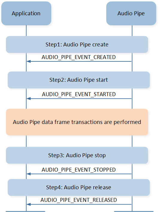
The operating principle of application mainly describes the detailed interaction flow between Audio Pipe and application.
The application calls audio_pipe_create() to create an Audio Pipe. After the successful
creation of the Audio Pipe, the application will receive the AUDIO_PIPE_EVENT_CREATED event.
Then, the application can call the audio_pipe_start() to start the Audio Pipe and the
application will receive the AUDIO_PIPE_EVENT_STARTED event. After that, the application can
start the processing and converting of data with DSP. Similarly, once the data conversion is
completed, the application calls the audio_pipe_stop() interface to stop the Audio Pipe and
waits for the AUDIO_PIPE_EVENT_STOPPED event. Finally, the Audio Pipe can be released through
the audio_pipe_release() interface.
Application Pipe Flow
The diagram below shows the detailed data frame transactions of Audio Pipe. The first batch of data
is sent by the application, and the subsequent filling and draining of data are driven by interrupts
sent from the DSP. The Audio Pipe will notify the application of the AUDIO_PIPE_EVENT_DATA_FILLED
and AUDIO_PIPE_EVENT_DATA_IND events, so that the application can fill or drain data.
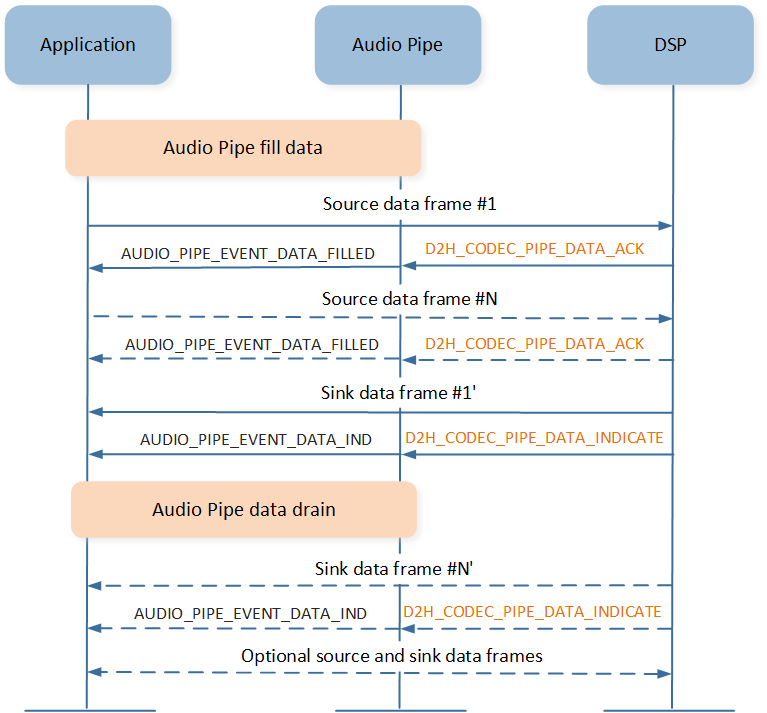
Application Pipe Data Transaction
When dealing with multiple Audio Pipe instances, the process for the Prime Pipe is the same as
previously described. The interaction flow between the Auxiliary Pipe and the application can be
referenced in the diagram below. Once the Auxiliary Pipe has been created, the application can
choose to add a Mixer point or a Tee point. The specific meanings of Mixer and Tee can refer to
DSP Module Process. After the application receives the AUDIO_PIPE_EVENT_MIXED
event, it can start the Auxiliary Pipe and then enter the data processing and conversion process
between the application and the DSP. Similarly, once the data processing is completed, the
application needs to remove the added Mixer point or Tee point before stopping and releasing the
Auxiliary Pipe. Then the Auxiliary Pipe can be stopped and released.
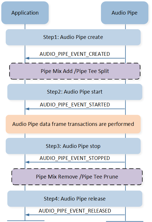
Application Pipe Mix
Note
If the Prime Pipe and the Auxiliary Pipe have not been demixed, the Auxiliary Pipe must be released before releasing the Prime Pipe.
After both the Prime Pipe and Auxiliary Pipe have started, the application can begin filling data.
As seen in the diagram below, both the Prime Pipe and Auxiliary Pipe need to send data to the DSP
at this point. However, because the application has added a Mixer point, the data streams from the
Prime Pipe and Auxiliary Pipe will be mixed together and encoded into a single stream sent to the
application. This means that the application will only receive the AUDIO_PIPE_EVENT_DATA_IND event
from the Prime Pipe, and the data sent to the application will follow the format of sink endpoint
set by the Prime Pipe.
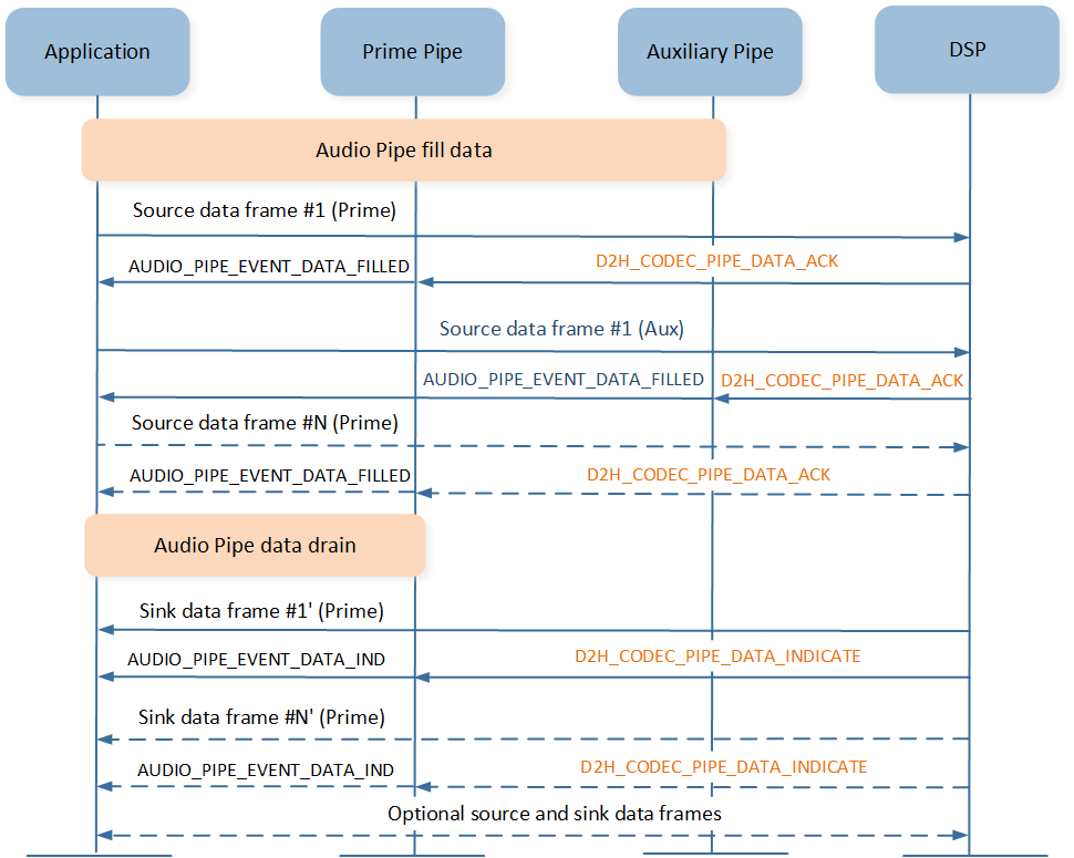
Application Pipe Mix Data Transaction
API Usage
Below are the application programming APIs provided by the Audio Pipe component, along with a brief introduction and precautions for their usage.
-
To create an Audio Pipe for coder conversion, the following parameters need to be set correctly. The stream mode can refer to
T_AUDIO_STREAM_MODE. Direct data mode bypasses the buffer management procedure, and then fills data into or drains data from the low level hardware, which is implemented for these low latency, real time and isochronous streaming scenarios. If the stream mode is set toAUDIO_STREAM_MODE_DIRECT, the DSP will no longer send data fill interrupts; instead, the flow control of data transmission will be managed by the application. Corresponding format info can refer toT_AUDIO_FORMAT_INFO. The sample code ofaudio_pipe_create()andaudio_pipe_start()is shown below:bool app_audio_pipe_create(uint8_t src_type, uint8_t snk_type) { T_AUDIO_FORMAT_INFO src_info; T_AUDIO_FORMAT_INFO snk_info; src_info.type = (T_AUDIO_FORMAT_TYPE)src_type; switch (src_type) { case AUDIO_FORMAT_TYPE_PCM: { src_info.frame_num = 1; src_info.attr.pcm.sample_rate = 48000; src_info.attr.pcm.frame_length = 240; src_info.attr.pcm.chann_num = 2; src_info.attr.pcm.bit_width = 16; } break; ...... } switch (snk_type) { case AUDIO_FORMAT_TYPE_SBC: { snk_info.frame_num = 6; snk_info.attr.sbc.subband_num = 8; snk_info.attr.sbc.bitpool = 0x22; snk_info.attr.sbc.sample_rate = 48000; snk_info.attr.sbc.block_length = 16; snk_info.attr.sbc.chann_mode = AUDIO_SBC_CHANNEL_MODE_JOINT_STEREO; snk_info.attr.sbc.allocation_method = 0; } break; ...... } audio_pipe_handle = audio_pipe_create(AUDIO_STREAM_MODE_NORMAL, src_info, snk_info, 0, app_audio_pipe_callback); if (audio_pipe_handle != NULL) { audio_pipe_start(audio_pipe_handle); } }
Note
The frame number parameter of the format info on both the source endpoint and the sink endpoint needs to be set appropriately. Currently, only the SBC coder supports multiple frames.
The frame number is a preset value. For the source endpoint, it indicates the frames the application expects to be contained in a packet. The DSP allocates a buffer of the corresponding size based on the frame number to store the data. For the sink endpoint, it indicates the frames the application expects to be contained in a packet. The playback time of a packet is determined by the frame size, sample rate, and frame number. The formula is as follows:
t = frame_size(sample_per_channel)/sample_rate*frame_num
Using an AAC coder to SBC coder conversion as an example, we will specifically discuss how to set the frame number. The concrete configurations of the coders are shown in the table.
Codec Type Parameters Coder Type
Frame Size
Sample Rate
Frame Num
AUDIO_FORMAT_TYPE_AAC1024
44100
1
AUDIO_FORMAT_TYPE_SBC128
48000
6
The playback durations for a single AAC packet and a single SBC packet are as follows:
t1 = 1024 / 44.1 * 1 = 23.2 ms
t2 = 128 / 48 * 6 = 16 ms
To avoid the application frequently handling DSP interrupts, the playback duration of an AAC packet and an SBC packet need to be as similar as possible. We can observe that if the frame number for SBC coder is set to 1, then the playback duration of one SBC packet is
t2' = 128 / 48 *1 = 2.67ms, so that for each AAC packet sent by the application, it will receive approximatelyt1 / t2 = 23.2 / 2.67 = 8SBC packets. This requires the application to frequently handle interrupts from the DSP, which is not very friendly for the application. Therefore, it is more reasonable to set the frame number to 6.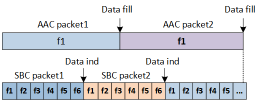
Frame Number Diagram
-
After the Audio Pipe is started, the application can stop, and then release the Audio Pipe following the flow of Operating Principle. The sample code is shown below:
bool app_audio_pipe_stop(T_AUDIO_PIPE_HANDLE handle)
{
   if (handle != NULL)
   {
         return audio_pipe_stop(handle);
   }

   return false;
}

static bool app_src_play_pipe_cback(T_AUDIO_PIPE_HANDLE handle,
                                    T_AUDIO_PIPE_EVENT  event,
                                    uint32_t            param)
{
   switch (event)
   {
   ......
   case AUDIO_PIPE_EVENT_STARTED:
   {
         a2dp_snk_pipe_play.fill_state = SNK_PIPE_STATE_STARTED;
         app_src_play_pipe_fill_data();
   }
   break;

   case AUDIO_PIPE_EVENT_STOPPED:
   {
         audio_pipe_release(handle);
   }
   break;

   case AUDIO_PIPE_EVENT_RELEASED:
   {
         if (a2dp_snk_pipe_play.p_fill_buf != NULL)
         {
            free(a2dp_snk_pipe_play.p_fill_buf);
            a2dp_snk_pipe_play.p_fill_buf = NULL;
            a2dp_snk_pipe_play.fill_seq = 0;
         }

         if (a2dp_snk_pipe_play.p_drain_buf != NULL)
         {
            free(a2dp_snk_pipe_play.p_drain_buf);
            a2dp_snk_pipe_play.p_drain_buf = NULL;
         }
            a2dp_snk_pipe_play.handle = NULL;
   }
         break;
   }
}
-
The application can get the current Audio Pipe gain and set Audio Pipe gain dynamically. The sample code is shown below:
bool a2dp_src_stream_volume_set(uint8_t volume)
{
   bool ret = false;
   if (volume > max_gain_level)
   {
         volume = max_gain_level;
   }
   uint16_t gain_val = a2dp_gain_table[app_cfg_nv.audio_gain_level[cur_pair_idx]];
   APP_PRINT_INFO3("a2dp_src_stream_volume_set,volume:%d,min:%d,max:%d",
                     volume, min_gain_level, max_gain_level);
   if (audio_pipe_handle != NULL)
   {
         app_cfg_nv.audio_gain_level[cur_pair_idx] = volume;
         ret = audio_pipe_gain_set(audio_pipe_handle, gain_val, gain_val);
   }

   return ret;
}
-
Upon receiving the
AUDIO_PIPE_EVENT_DATA_FILLEDandAUDIO_PIPE_EVENT_DATA_INDevents, the application can fill data into or drain data from the low level hardware. The sample code is shown below:static bool app_src_play_pipe_cback(T_AUDIO_PIPE_HANDLE handle, T_AUDIO_PIPE_EVENT event, uint32_t param) { switch (event) { case AUDIO_PIPE_EVENT_DATA_IND: { if (a2dp_snk_pipe_play.play_state == SNK_PLAY_STATE_START) { app_src_play_pipe_handle_data_ind(); } } break; case AUDIO_PIPE_EVENT_DATA_FILLED: { if (a2dp_snk_pipe_play.play_state == SNK_PLAY_STATE_START) { a2dp_snk_pipe_play.fill_state = SNK_PIPE_STATE_FILLED; app_src_play_pipe_fill_data(); } } break; } ...... } static uint8_t app_src_play_pipe_fill_data(void) { uint8_t res = SRC_PLAY_PIPE_MGR_SUCCESS; if (a2dp_snk_pipe_play.p_fill_buf == NULL) { res = SRC_PLAY_PIPE_MGR_MEM_ERROR; return res; } else { if (res == SRC_PLAY_PIPE_MGR_SUCCESS) { flag_pipe_get_data_empty = false; if (!audio_pipe_fill(a2dp_snk_pipe_play.handle, 0, a2dp_snk_pipe_play.fill_seq, AUDIO_STREAM_STATUS_CORRECT, 5, a2dp_snk_pipe_play.p_fill_buf, a2dp_snk_pipe_play.fill_len)) { res = SRC_PLAY_PIPE_MGR_PIPE_FILL_ERROR; } else { a2dp_snk_pipe_play.fill_seq++; a2dp_snk_pipe_play.fill_state = SNK_PIPE_STATE_FILLING; } } else { flag_pipe_get_data_empty = true; } free(a2dp_snk_pipe_play.p_fill_buf); } APP_PRINT_INFO1("app_src_play_pipe_fill_data: res %d", res); return res; } static void app_src_play_pipe_handle_data_ind(void) { uint8_t frame_num = 0; uint16_t len = 0; uint16_t seq = 0; uint32_t timestamp = 0; T_AUDIO_STREAM_STATUS status; bool ret = audio_pipe_drain(a2dp_snk_pipe_play.handle, ×tamp, &seq, &status, &frame_num, a2dp_snk_pipe_play.p_drain_buf, &len); if (!ret) { APP_PRINT_ERROR0("app_src_play_pipe_handle_data_ind: drain failed"); return; } if (app_src_play_get_src_route() == PLAY_ROUTE_A2DP) { ret = app_src_play_a2dp_handle_data(a2dp_snk_pipe_play.p_drain_buf, len, frame_num); } else if (app_src_play_get_src_route() == PLAY_ROUTE_BIS || app_src_play_get_src_route() == PLAY_ROUTE_CIS) { ...... } }
Note
The
seq_numofaudio_pipe_fill()should be continuous and theframe_numofaudio_pipe_fill()means the actual frame number per transaction.
See Also
Please refer to the relevant API Reference: