The purpose of this document is to describe how to use the Audio Route module in the MCUConfig Tool.
The Audio Route capability of each IC can be demonstrated using the MCUConfig Tool. Customers can
configure the routing relationship of each audio stream by using the MCUConfig Tool.
The following topics are included to help users to use the Audio Route module.
Audio Route indicates the static configuration of the physical data path. The Audio Route module
consists of SPORT configuration, Endpoint configuration, and Logical IO
configuration. The Audio Route module is classified according to the Audio Category.
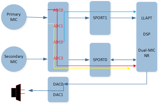
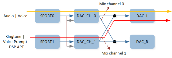
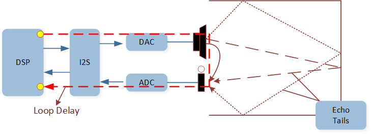
The figure shows a simplified Audio Route path between the Codec and DSP.
As shown in the figure, the data collected by the microphone passes through an ADC
channel of the Codec and flows to a SPORT RX channel to reach the DSP. After the data is processed
by the DSP, it passes through a SPORT TX channel and then through the DAC
channel of the Codec, finally playing out through the specific speaker.
The main function of the Audio Route module is to configure SPORT and Logical IO related
parameters for an Audio Route path. The SPORT controls the inflow and outflow of multiple stream
routing paths. These stream routing paths should have the same configurations, including sample
rate, data length, channel length, and channel mode. The Logical IO defines the functional
attributes of the stream routing path.
Audio Category is used to classify all streams transferred between the Host and the Controller.
The Controller is isolated from the physical peripheral and requires Logical IO to obtain the stream
routing context. The Host represents a physical component that is MCU or DSP.
The streams have the same control flows, usage scenarios, and functionalities.
Logical IO refers to the Logical input and output functions
provided by the DSP. It encompasses Primary SPK, Secondary SPK, Primary MIC, Secondary MIC, Fusion MIC,
Bone MIC, External MIC, Internal MIC, Primary AUX, Secondary AUX, Primary Reference MIC, Secondary Reference MIC,
Primary Reference SPK, and Secondary Reference SPK. Logical IO is classified according to the Audio Category.
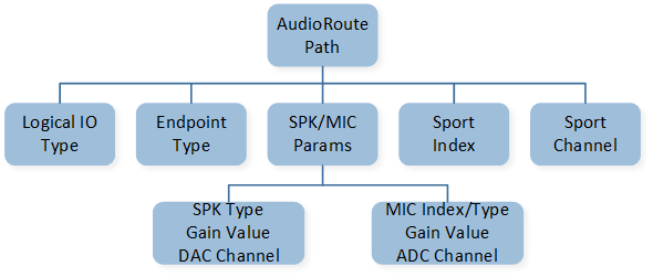
The figure illustrates that an Audio Route path comprises several components, namely Logical IO
type, Endpoint type, SPK and MIC parameters, SPORT index, and SPORT channel. The SPK parameter
encompasses SPK type, SPK gain, and DAC channel. On the other hand, the MIC parameter consists of
MIC index, MIC type, MIC gain, and ADC channel.
The table shows the parameter description of Audio Route path.
The Audio Route module is mainly used to configure related parameters of SPORT and Logical IO
parameters of the physical data path. The main configurable functions are as follows:
Configure ADC Gain for the device MIC.
Configure the SPORT hardware parameters.
Configure the Codec Mixing function.
Configure Logical IO parameters for the audio streams.
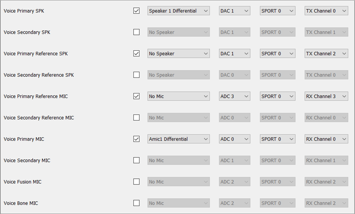
If the VoicePrimaryMIC is configured under the Voice Category and Amic1 Differential is selected, the ADCGain
value of Amic1 Differential needs to be configured.
When clicking the Set ADC Gain button, a configuration box for ADCGain will appear. From there,
the Analog Boost Gain can be selected by using the drop-down box provided for Amic1 Differential. It's important
to note that the analog boost gain for the physical MIC or AUX can be set to values of 0/3/6/9/12/18/24/30dB.
Note
MIC ADCGain can be adjusted using the Set ADC Gain button only if AMIC is selected.
AUX ADCGain can be adjusted by setting the Set ADC Gain button only when AUX is selected.
The current SPORT hardware parameters are all configured by default. Unless there are specific
requirements, there is no need to modify these settings.
In the event that customers need to configure the SPORT parameters, it is recommended to involve
a developer who can handle the configuration process and provide the necessary parameters to the
customers. Please note that the default configuration for SPORT may differ depending on
the specific IC being used.
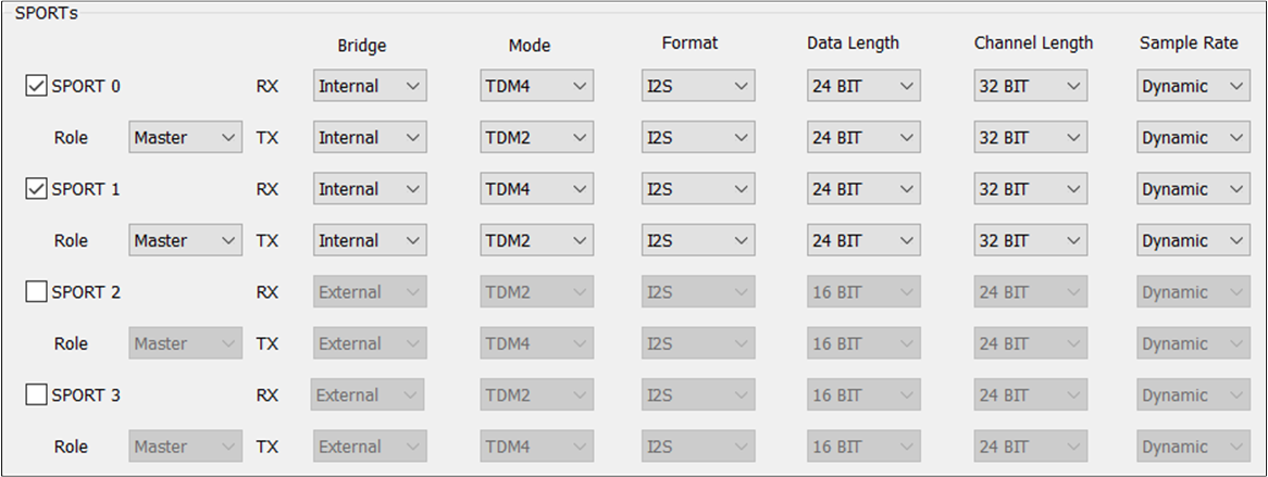
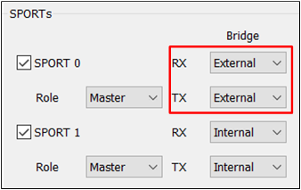
The figure shows how to configure SPORT parameters.
SPORT 0/1/2/3: Enable the corresponding index's SPORT by selecting this option.
Role: Configure the Role of the SPORT. The options are Master or Slave.
RX/TX Bridge: Configure the SPORT to support single-direction TX and RX configurations. The options are Internal or External. If External is selected, the corresponding PINMUX can be configured in the HW Feature tab.
RX/TX Mode: Configure the transfer mode in the TX and RX directions. The options are TDM2/4/6/8.
RX/TX Format: Configure the format of the SPORT data in the TX and RX directions. The options are I2S/Left Justified/PCM_A/PCM_B.
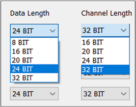
RX/TX Data Length: Configure the data length in the TX and RX directions of the SPORT. The options are 8/16/20/24/32 BIT.
RX/TX Channel Length: Configure the length of the channel in the TX and RX directions. The options are 16/20/24/32 BIT.
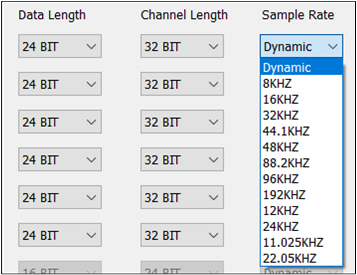
RX/TX Sample Rate: Configure the sample rate in the TX and RX directions of the SPORT. The options are 8/16/32/44.1/48/88.2/96/192/12/24/11.025/22.05 KHz.
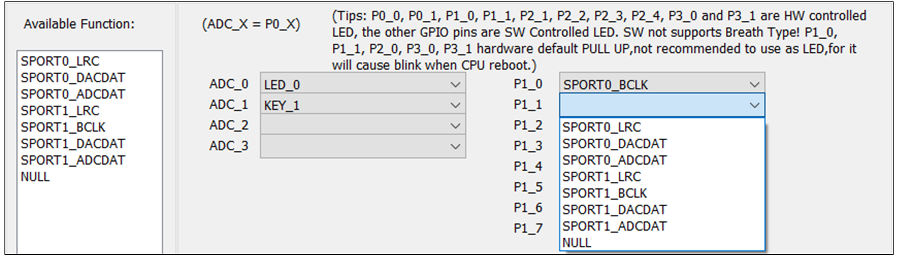
To configure an external device, use the TX and RX drop-down boxes in the SPORTBridge field to
specify the external device's configuration in one direction. For instance, let's say TX and RX need
to be configured in the Bridge field of SPORT0 as External. In this case, the corresponding
PINMUX of SPORT0_LRC, SPORT0_BCLK, SPORT0_DACDAT, and SPORT0_ADCDAT will also need to be
configured in the HW Feature tab.
Note
When the Role field is set to Master, the TX and RXBridge field allows users to freely select External/Internal. When Role is set to Slave, the TX and RX of the Bridge field can only be changed to the fixed value External.
RTL87x3E and RTL87x3EP: For SPORT0/1, you can configure the Bridge field based on the Role field. For SPORT2, the TX and RX of its Bridge field is a fixed value External, regardless of its Role value.
RTL87x3D: For SPORT0/1/2, you can configure the Bridge field based on the Role field. For SPORT3, the TX and RX of its Bridge field is the fixed value External, regardless of its Role value.
The SPORT Data Length is typically configured by default. However, if there is a special
requirement, you may need to configure the Data Length fields for both the TX and RX in the SPORTs.
Note
For RTL87x3E, RTL87x3EP, and RTL87x3D, it is recommended to set the Data Length to 24BIT.
By default, the SPORT Channel Length is configured automatically. However, if there is a special
requirement, you may need to manually configure the Channel Length fields for both TX and RX in the
SPORTs.
Note
For RTL87x3E, RTL87x3EP and RTL87x3D, it is recommended to set the Channel Length to 32BIT.
The default configuration sets the SPORT Sample Rate automatically. However, if there are
specific requirements, it may be necessary to manually configure the TX and RXSample Rate fields in the
SPORTs. In the configuration, Dynamic indicates that the physical data flow uses its own sample
rate, which can vary. On the other hand, other fields indicate that the physical data flow uses a
fixed sample rate.
In the depicted scenario shown in the figure, where Audio or Voice and Voice Prompt are mixed
and played on DAC0, the tool configuration allows configuring Codec Mixing function. With Codec Mixing,
selection of the mix path for DAC0 and DAC1 can be done according to requirements. Please note that the
default configuration of the Codec mixing field is already set, but there is the flexibility to
modify it based on specific needs.
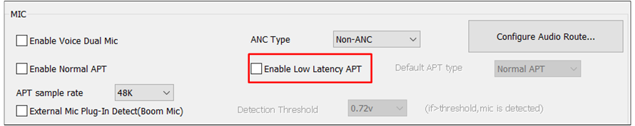
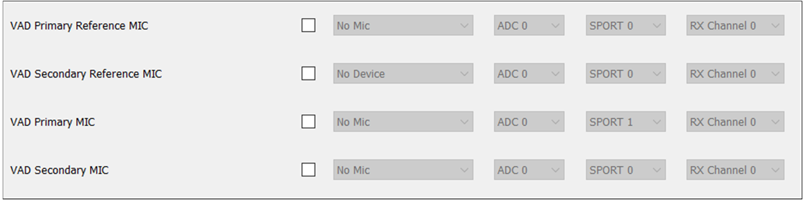
The Audio Logical Device supports the configuration of Logic IO parameters for data streams such as
Audio, Voice, Record, Line, Ringtone, Voice Prompt, APT, LLAPT, ANC and VAD.
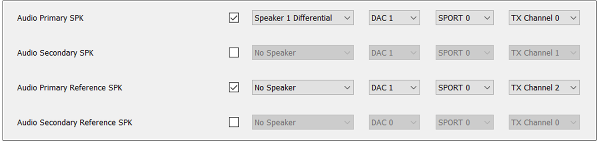
The Audio Category supports the following Logical IO parameters:
AudioPrimarySPK is used to set the Audio physical path of the Primary SPK.
AudioSecondarySPK is used to set the Audio physical path of the Secondary SPK.
AudioPrimaryReferenceSPK is used to set the Audio physical AEC loopback path of the Primary SPK.
AudioSecondaryReferenceSPK is used to set the Audio physical AEC loopback path of the Secondary SPK.
Note
AudioPrimarySPK must at least be selected and configured correctly.
Both AudioPrimarySPK and AudioSecondarySPK need to be selected and configured at the same time to achieve the stereo effect.
When the RecordPrimaryReferenceMIC and RecordSecondaryReferenceMIC corresponding to the Record Category are also configured, the AEC loopback path of Audio and Record can be really connected. AEC means the linear removal of echo signal mixing in microphone input without affecting the quality of the desired speech signal.
When the VoicePrimaryReferenceSPK and VoicePrimaryReferenceMIC corresponding to the Voice Category, or when the VoiceSecondaryReferenceSPK and VoiceSecondaryReferenceMIC are configured, the AEC loopback path is actually connected.
The Record Category supports the following Logical IO parameters:
RecordPrimaryMIC is used to set the Record physical path of the Primary MIC.
RecordSecondaryMIC is used to set the Record physical path of the Secondary MIC.
RecordPrimaryReferenceMIC is used to set the Record physical AEC loopback path of the Primary MIC.
RecordSecondaryReferenceMIC is used to set the Record physical AEC loopback path of the Secondary MIC.
RecordLeftAUX is used to set the Record physical path for the AUX Left channel.
RecordRightAUX is used to set the physical path of the Record AUX Right channel.
RecordFusionMIC is used to set the Record physical path of Fusion MIC.
RecordBoneMIC is used to set the Record physical path of the Bone Sensor MIC.
Note
RecordPrimaryMIC or RecordLeftAUX must be selected and configured correctly.
When the PrimaryReferenceSPK and SecondaryReferenceSPK corresponding to Audio Category, Ringtone Category, or Voice Prompt Category are configured, the AEC loopback path for Audio and Record, Ringtone and Record, or Voice Prompt and Record is open.
The Line Category supports the following Logical IO parameters:
Line-inPrimarySPK is used to set the Line physical path of the Primary SPK.
Line-inSecondarySPK is used to set the Line physical path of the Secondary SPK.
Line-inPrimaryReferenceSPK is used to set the Line physical AEC loopback path of the Primary SPK.
Line-inSecondaryReferenceSPK is used to set the Line physical AEC loopback path of the Secondary SPK.
Line-inPrimaryReferenceMIC is used to set the Line physical AEC loopback path of the Primary MIC.
Line-inSecondaryReferenceMIC is used to set the Line physical AEC loopback path of the Secondary MIC.
Line-inPrimaryMIC is used to set the Line physical path of the Primary MIC.
Line-inSecondaryMIC is used to set the Line physical path of the Secondary MIC.
Line-inLeftAUX is used to set the Line physical path of the AUX Left channel.
Line-inRightAUX is used to set the Line physical path of the AUX Right channel.
Note
Line-inPrimarySPK and Line-inPrimaryMIC must be selected and configured correctly.
When the Line-inPrimaryReferenceSPK and Line-inPrimaryReferenceMIC correspond to the Line Category, or when the Line-inSecondaryReferenceSPK and Line-inSecondaryReferenceMIC are configured, the loopback path of the AEC is actually connected.
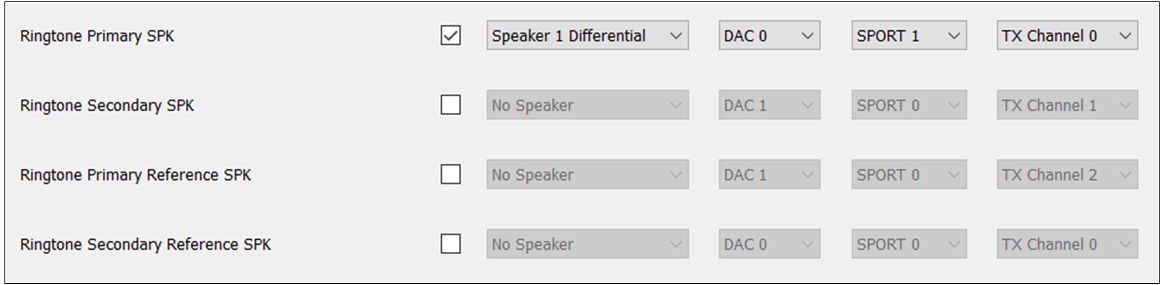
The Ringtone Category supports the following Logical IO parameters:
RingtonePrimarySPK is used to set the ringtone physical path of the Primary SPK.
RingtoneSecondarySPK is used to set the ringtone physical path of the Secondary SPK.
RingtonePrimaryReferenceSPK is used to set the ringtone physical AEC loopback path of the Primary SPK.
RingtoneSecondaryReferenceSPK is used to set the ringtone physical AEC loopback path of the Secondary SPK.
Note
RingtonePrimarySPK must at least be selected and configured correctly.
When the RecordPrimaryReferenceMIC and RecordSecondaryReferenceMIC corresponding to the Record Category are also configured, the AEC loopback path of Ringtone and Record is really open.
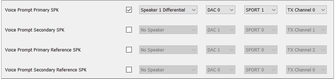
The Voice Prompt Category supports the following Logical IO parameters:
VoicePromptPrimarySPK is used to set the Voice Prompt physical path of the Primary SPK.
VoicePromptSecondarySPK is used to set the Voice Prompt physical path of the Secondary SPK.
VoicePromptPrimaryReferenceSPK is used to set the physical AEC loopback path of the Voice Prompt in the Primary SPK.
VoicePromptSecondaryReferenceSPK is used to set the physical AEC loopback path of the Voice Prompt in the Secondary SPK.
Note
VoicePromptPrimarySPK must at least be selected and configured correctly.
When the RecordPrimaryReferenceMIC and RecordSecondaryReferenceMIC corresponding to the Record Category are also configured, the AEC loopback path of the Voice Prompt and the Record is really open.
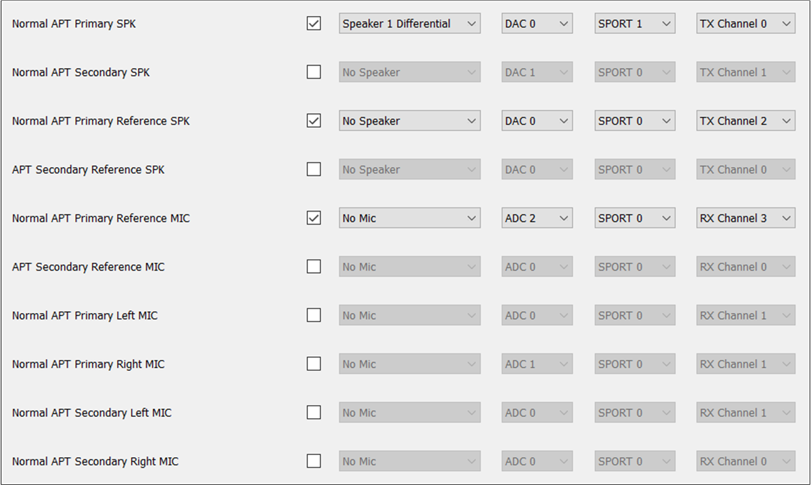
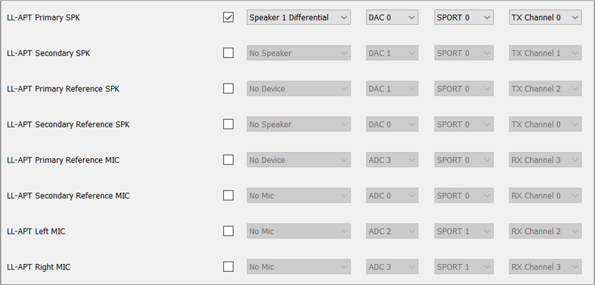
When APTPrimaryReferenceSPK and APTPrimaryReferenceMIC correspond to APT Category, or when APTSecondaryReferenceSPK and APTSecondaryReferenceMIC are configured, the AEC loopback path can be really opened.
When the LL-APTPrimaryReferenceSPK and LL-APTPrimaryReferenceMIC correspond to the LL-APT Category, or when the LL-APTSecondaryReferenceSPK and LL-APTSecondaryReferenceMIC are configured, the AEC loopback path can be really connected.
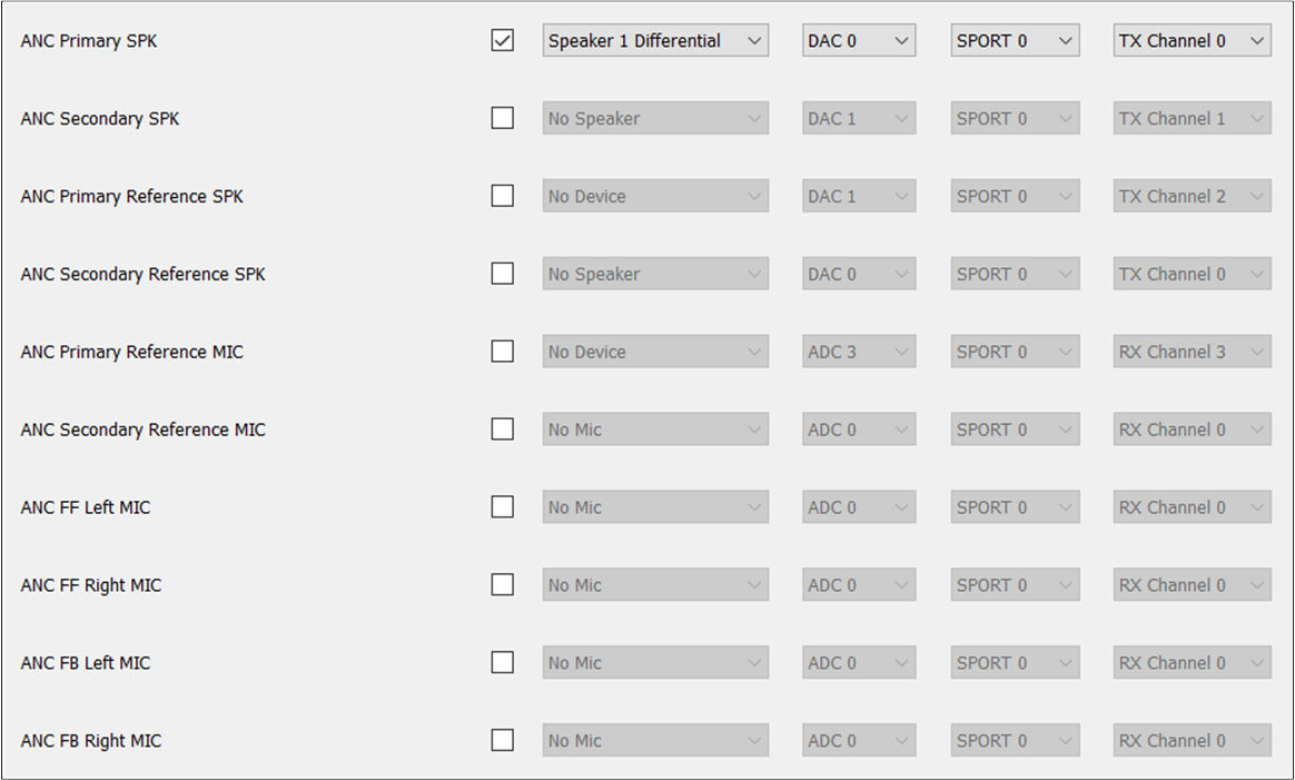
The ANC Category supports the following Logical IO parameters:
ANCPrimarySPK is used to set the ANC physical path of the Primary SPK.
ANCSecondarySPK is used to set the ANC physical path of the Secondary SPK.
ANCPrimaryReferenceSPK is used to set the ANC physical AEC loopback path of the Primary SPK.
ANCSecondaryReferenceSPK is used to set the ANC physical AEC loopback path of the Secondary SPK.
ANCPrimaryReferenceMIC is used to set the ANC physical AEC loopback path of the Primary MIC.
ANCSecondaryReferenceMIC is used to set the ANC physical AEC loopback path of the Secondary MIC.
ANCFFLeftMIC is used to set the ANC physical path with the Feedforward Left MIC.
ANCFFRightMIC is used to set the ANC physical path with the Feedforward Right MIC.
ANCFBLeftMIC is used to set the ANC physical path of the Feedback Left MIC.
ANCFBRightMIC is used to set the ANC physical path of the Feedback Right MIC.
Note
ANCPrimarySPK and ANCFFLeftMIC must at least be selected and configured correctly.
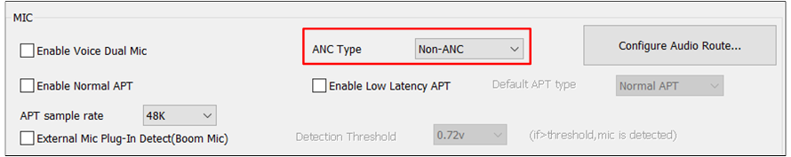
ANCFFMIC can be configured only when ANC Type in HW Feature tab is set to ANC FF Only. ANCFBMIC can be configured only when ANC FB Only. when ANC Type is set to ANC Hybrid, ANCFFMIC and ANCFBMIC can be configured simultaneously.
When ANCPrimaryReferenceSPK and ANCPrimaryReferenceMIC corresponding to ANC Category, or when the ANCSecondaryReferenceSPK and ANCSecondaryReferenceMIC are well configured, the AEC loopback path can be really opened.
AEC Reference Function: Linear removal of echo signal mixing in microphone input without affecting the quality of
the desired speech signal. For tool configuration, when you need to configure the AEC Reference function,
select PrimaryReferenceSPK and PrimaryReferenceMIC of Audio Category. The AEC Reference configuration
can be performed in the following two cases:
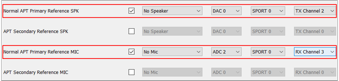
The figure shows two types of AEC Reference Function.
1. Case 1: Reference signal from HW Codec DAC[5M]=>ADC[5M]=>SPORT RX=>DSP.
In this case, select PrimaryReferenceSPK and PrimaryReferenceMIC and set them as
No Speaker and No Mic for tool configuration.
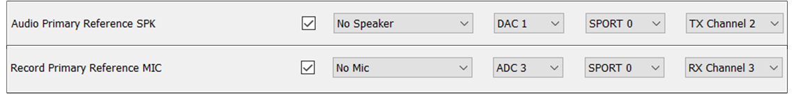
Note
The figure shows the tool configuration of AEC Reference Function between Audio and Record.
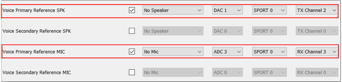
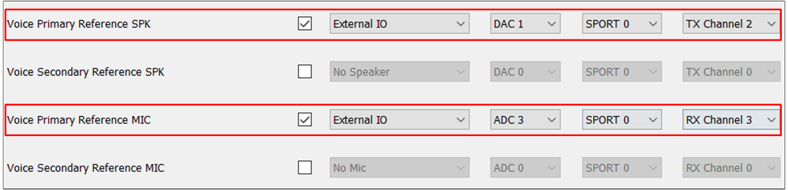
2. Case 2: Reference signal from External Codec DAC=>ADC=>SPORT RX=>DSP.
In this case, for tool configuration, select PrimaryReferenceSPK and configure PrimaryReferenceMIC
as External IO and External IO.
Note
The figure shows the tool configuration of AEC Reference Function for the external case.