LE DTM
The DTM application is used to control the DUT and provides a report back to the Tester.
Overview
Direct Test Mode is used to test the RF PHY layer of Bluetooth Low Energy devices. DTM shall be set up by one of the two alternative methods: Over HCI or through a 2-wire UART interface. Each DUT shall implement one of the two DTM methods.
In this document, DUT implements the second method, which is set through a 2-wire UART interface. The test framework of through 2-wire UART interface is shown below:
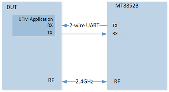
Test Framework
DUT runs DTM application, and test equipment of MT8852B sends DTM commands to DUT.
DTM application analyzes commands and invokes APIs to send and receive packets from MT8852B.
DTM application collects test results and sends them to MT8852B by DTM events.
MT8852B judges and displays the results.
Transmitter Test
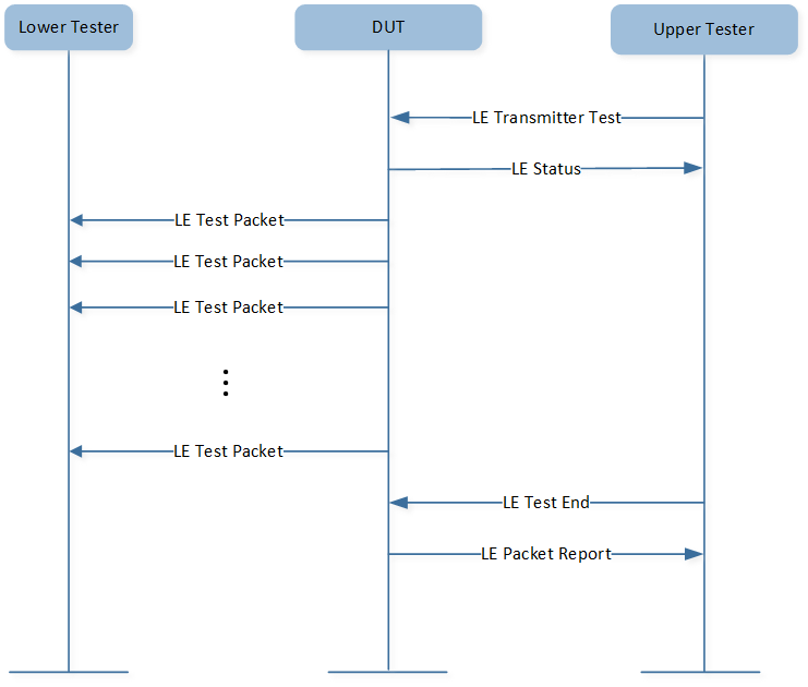
Transmitter Test
Upper tester sends command to DUT to order it to transmit test packets to lower tester. DUT reports event to upper tester after transmit procedure terminates.
-
Output Power Test
The MT8852B transmits a test control message over the RS232, USB, or 2-wire interface to instruct the DUT to transmit reference test packets. The MT8852B measures the average power of the received packets over at least 20% to 80% of the duration of the burst.
-
Carrier & Drift Test
The carrier drift test performs a frequency drift measurement over the length of the packet received. The carrier frequency offset is measured similarly to the basic rate initial carrier test, but on the eight preamble bits in the low energy reference packet.
-
Modulation Index Test
This test measures the modulation characteristics on the DUT output for each of the selected frequency ranges (LOW, MEDIUM and HIGH).
Receiver Test
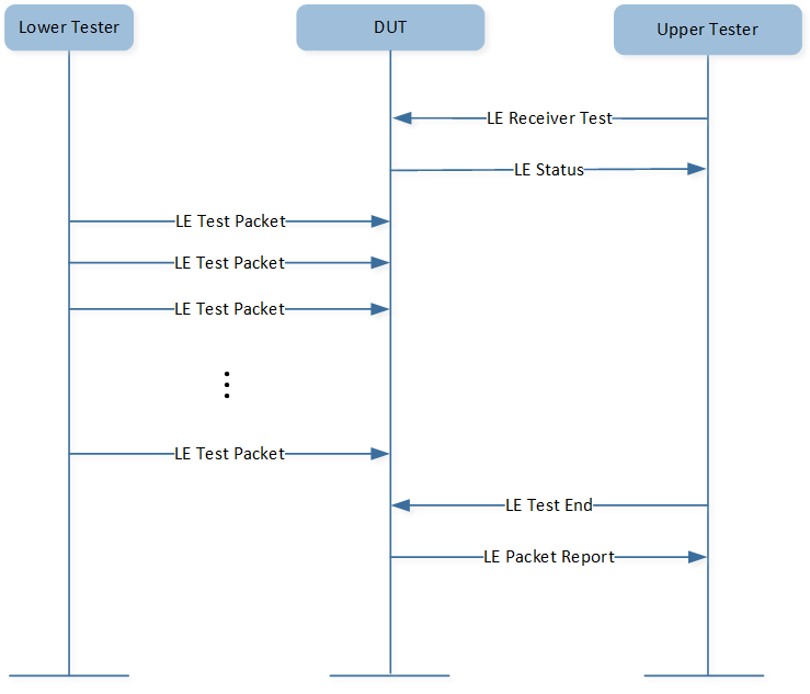
Receiver Test
Upper tester sends command to DUT to order DUT to prepare to receive test packets from lower tester. Lower tester sends test packets to DUT, and DUT reports event to upper tester after receive procedure terminates.
-
Sensitivity Test
After sending a test control to prepare the DUT, the MT8852B sends LE reference packets to the DUT. The number of packets the DUT received is counted and this data is then read by the MT8852B over the 2-wire connection.
-
PER Integrity
The MT8852B sends a random even number of LE reference packets to the DUT at -30 dBm with a PRBS 9 payload. The CRC value for the packets is alternated between a valid and invalid value. The DUT counts the number of received packets and this value is read by the MT8852B over the 2-wire interface for frame error rate (FER) calculation. The test is repeated three times at the frequency selected.
-
Maximum Input Power Test
After sending a test control, the MT8852B sends LE reference packets to the DUT at -10 dBm. The number of packets received by the DUT is counted and this data is then read by the MT8852B via the 2-wire connection.
Requirements
The sample supports the following development kits:
Hardware Platforms |
Board Name |
Build Target |
|---|---|---|
RTL87x3E HDK |
RTL87x3E EVB |
|
RTL87x3D HDK |
RTL87x3D EVB |
|
Note
To purchase EVB, please visit https://www.realmcu.com/en/Home/Shop.
When built for an xxx_4M_xxx build target, the sample is configured to compile and run with a 4M flash map.
When built for an xxx_8M_xxx build target, the sample is configured to compile and run with an 8M flash map.
When built for an xxx_16M_xxx build target, the sample is configured to compile and run with a 16M flash map.
To quickly set up the development environment, refer to Quick Start.
Configurations
DTM enhanced test can be configured in src\sample\ble_dtm\app_flags.h, developers can configure according to actual needs.
#define F_BT_LE_5_0_SUPPORT 1
Building and Downloading
Detailed information about building and downloading can be found in Building and Downloading.
This sample can be found under sdk\board\evb\ble_dtm in SDK folder structure.
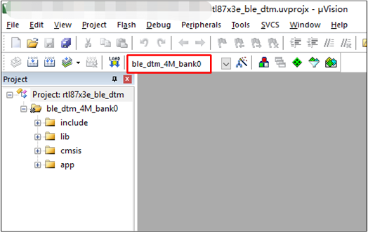
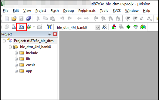
Take the project rtl87x3e_ble_dtm.uvprojx and target ble_dtm_4M_bank0 as an example,
to build and run the sample with Keil development environment, follow the steps listed below:
Open
rtl87x3e_ble_dtm.uvprojx.Choose the build target
ble_dtm_4M_bank0.
Choose Build Target
Build the target. After a successful compilation, the APP bin file
ble_dtm_bank0_MP-v0.0.0.0-xxx.binwill be generated in the directorybin\rtl87x3e\flash_4M_dualbank\bank0.
Target Building
Download the APP bin into the EVB board.
Experimental Verification
This section gives a brief introduction of test steps and test results in detail.
Preparation Phase
The preparation phase includes downloading the DTM application and connecting devices.
Downloading DTM Application
Compile and download DTM application to DUT.
Connecting DUT and MT8852B
The first step is to connect the DUT and MT8852B through the 2-wire UART by using RS232, the TX pin and RX pin of DUT should be connected with the same pin of RS232.
DTM application sets P3_1 as the TX pin of data UART and P3_0 as the RX pin of data UART by default.
#define DATA_UART_TX_PIN    P3_1
#define DATA_UART_RX_PIN    P3_0
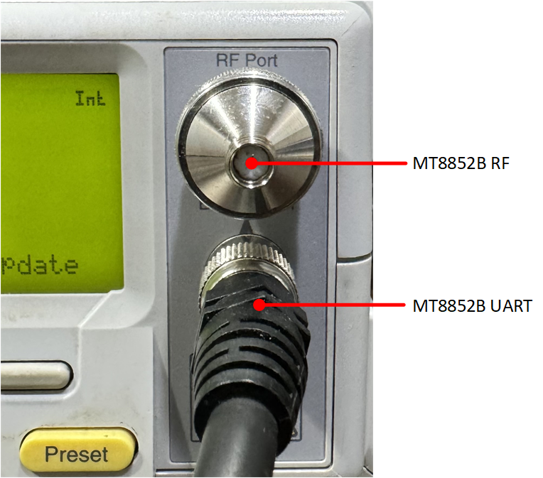
MT8852B UART
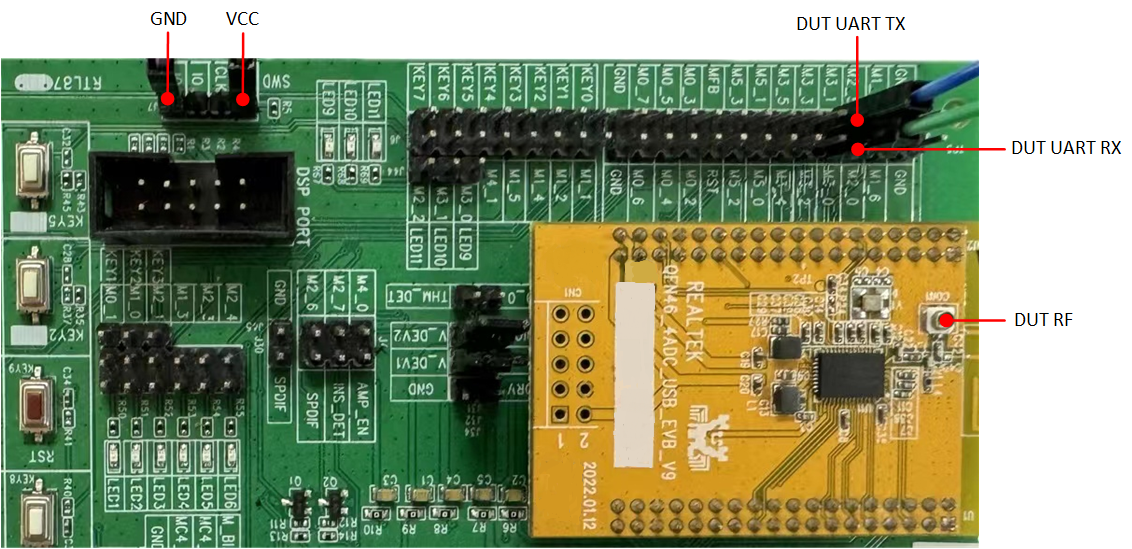
DUT UART
Testing Phase
The preparation phase includes configuring devices and running MT8852B.
Configuring DUT and MT8852B
As shown below, press the On/Standby button to start MT8852B, and then press the EUT addr button to modify the EUT address.

MT8852B Initiation
DUT implements DTM application based on 2-wire UART, so first press the Sel button, then choose BLE2WIRE as the Source.
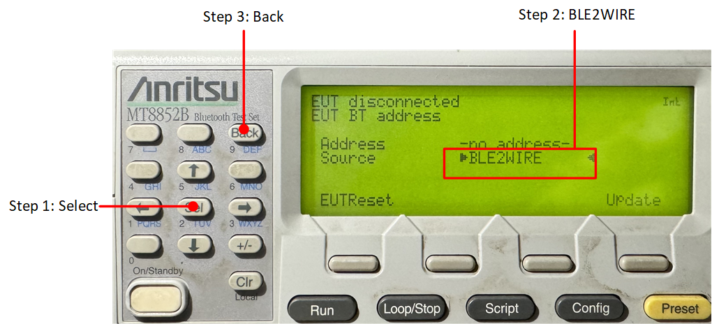
EUT Address
Press the Setup button to set Low energy script.
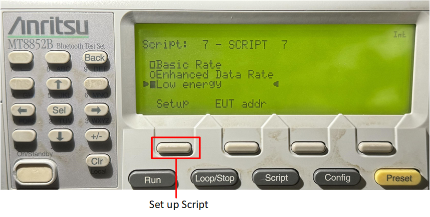
Low Energy Script
Running MT8852B
Run MT8852B based on cases to be tested.
-
Run All Test Cases
Press the Run button to run all test cases.
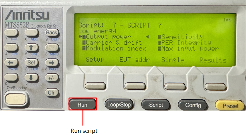
Test Scripts
-
Run Single Test Case
Choose the case that needs to be tested and then press the Single button and the Run button to run the single test case.
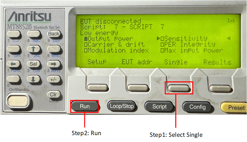
Test Single Script
Test Results
The passed test results are shown below. The letter P will display after the passed test case.
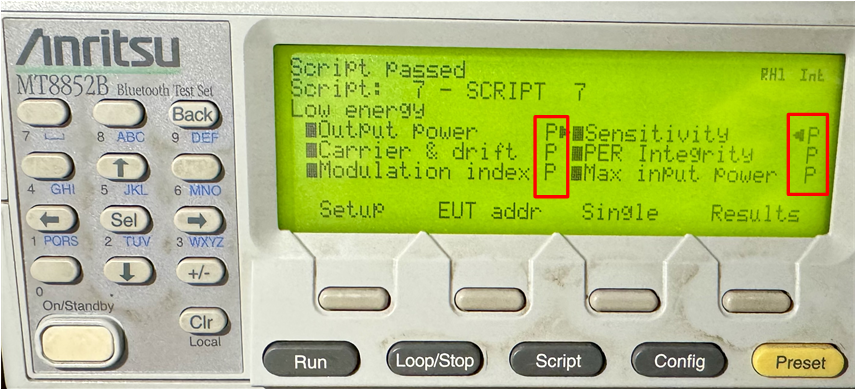
Test Result
Code Overview
This section shows the project and source code of the DTM application. The project sdk\board\evb\dtm\rtl87x3e_ble_dtm.uvprojx is utilized as an example. The overview will be introduced according to the following several parts:
The main function will be introduced in Initialization and Main Functions.
The GAP callback handler of the sample will be introduced in GAP Callback Handler.
Source Code Directory
Project directory:
sdk\board\evb\ble_dtm.Source code directory:
sdk\src\sample\ble_dtm.
Source files in the sample project are currently categorized into several groups as below.
└── ble_dtm_4M_bank0
    ├── include                  ROM UUID header files. Users do not need to modify it.
    ├── lib                      Includes all binary symbol files that user application is built on.
        ├── ROM.lib
        ├── upperstack_4M.lib
        ├── hal_utils.lib
        └── gap_utils.lib
    ├── cmsis                    The cmsis source code. Users do not need to modify it.
    ├── app                      The application source code.
        ├── main.c               Entry of application. Initialize parameters and register application message callback.
        ├── app_task.c           Create message queue and application task.
        └── dtm_app.c            Handle commands from MT8852B and return with events.
Initialization
main() function is invoked when the EVB is powered on and the chip is reset,
and it performs the following initialization functions:
int main(void)
{
    le_gap_init(0);
    gap_lib_init();
    app_le_gap_init();
    application_task_init();
    os_sched_start();

    return 0;
}
le_gap_init()function is used to initialize GAP and configure link number.app_le_gap_init()function is used to initialize the GAP parameters.
Main Functions
In dtm_app.c , UART0_Handler() receives commands from MT8852B.
void UART0_Handler(void)
{
   uint8_t uartdata[2] = {0, 0};
   uint8_t *p = uartdata;
   uint16_t command = 0;
   uint32_t int_status = 0;
   int_status = UART_GetIID(UART0);

   UART_INTConfig(UART0, UART_INT_RD_AVA | UART_INT_LINE_STS, DISABLE);

   switch (int_status)
   {
   case UART_INT_ID_TX_EMPTY:
      break;

   case UART_INT_ID_RX_LEVEL_REACH:

   case UART_INT_ID_RX_TMEOUT:
      while (UART_GetFlagState(UART0, UART_FLAG_RX_DATA_RDY) == SET)
      {
            UART_ReceiveData(UART0, p++, 1);
            if (p - uartdata > 2)
            {
               break;
            }
      }
      command = (uartdata[0] << 8) | uartdata[1];
      APP_PRINT_INFO1("FORM 8852B: 0x%x", command);
      dtm_test_req(command);
      break;

   case UART_INT_ID_LINE_STATUS:
      break;

   default:
      break;
   }

   UART_INTConfig(UART0, UART_INT_RD_AVA, ENABLE);
   return;
}
dtm_test_req() handles test commands from MT8852B, then invokes GAP APIs to start test.
void dtm_test_req(uint16_t command)
{
   uint8_t contrl = 0;
   uint8_t param = 0;
   uint8_t tx_chann = 0;
   uint8_t rx_chann = 0;
   uint8_t data_len = 0;
   uint8_t pkt_pl = 0;
   uint8_t cmd = (command & 0xc000) >> 14;
   uint16_t event  = 0;

   //the upper 2 bits of the data length for any Transmitter or Receiver commands following
   static uint8_t up_2_bits = 0;
   //physical to use
   static uint8_t phy = 1;
   //modulation index to use
   static uint8_t mod_idx = 0;
   //local supported features
   static uint8_t lcl_feats[GAP_LE_SUPPORTED_FEATURES_LEN] = {0};

   switch (cmd)
   {
   case 0:
      contrl = (command & 0x3f00) >> 8;
      param = (command & 0xfc) >> 2;

      switch (contrl)
      {
      case 0:
            if (param == 0)
            {
               up_2_bits = 0;
               phy = 1;
               mod_idx = 0;
            }
            else
            {
               event |= 1;
            }
            dtm_uart_send_bytes(event);
            break;
      ......
      case 5:
            /*
            8852B do not send these commands
               0x00 Read supportedMaxTxOctets
               0x01 Read supportedMaxTxTime
               0x02 Read supportedMaxRxOctets
               0x03 Read supportedMaxRxTime
            */
            break;
      default:
            break;
      }
      APP_PRINT_INFO3("dtm_test_req: up_2_bits 0x%x, phy 0x%x, mod_idx 0x%x", up_2_bits, phy, mod_idx);
      break;

   ......
   }
}
dtm_uart_send_bytes() sends event to MT8852B.
void dtm_uart_send_bytes(uint16_t event)
{
    uint8_t uartdata[2] = {0};
    uartdata[0] = (event & 0xff00) >> 8;
    uartdata[1] = event & 0xff;
    uint8_t *p_ch = uartdata;

    uint8_t i = 0;
    for (i = 0; i < 2; i++)
    {
        while (UART_GetFlagState(UART0, UART_FLAG_THR_EMPTY) != SET)
        {
            ;
        }
        UART_SendData(UART0, p_ch++, 1);
    }
}
GAP Callback Handler
app_gap_callback() function is used to handle GAP callback messages.
When test begins, the GAP Layer will use GAP_MSG_LE_DTM_ENHANCED_RECEIVER_TEST or GAP_MSG_LE_DTM_ENHANCED_TRANSMITTER_TEST message to inform application to perform Transmitter Test or Receiver Test. Sample code is listed as below:
T_APP_RESULT app_gap_callback(uint8_t cb_type, void *p_cb_data)
{

   T_APP_RESULT result = APP_RESULT_SUCCESS;
   T_LE_CB_DATA *p_data = (T_LE_CB_DATA *)p_cb_data;
   uint16_t status  = 0;
   uint16_t event = 0;
   APP_PRINT_INFO1("app_gap_callback: cb_type %d", cb_type);
   switch (cb_type)
   {
   ......
#if F_BT_LE_5_0_DTM_SUPPORT
   case GAP_MSG_LE_DTM_ENHANCED_RECEIVER_TEST:
#endif
      status = p_data->le_cause.cause;
      if (status == 0)
      {
            APP_PRINT_INFO2("app_gap_callback: event 0x%x, status 0x%x", (event & 0x8000) >> 15, event & 0x1);
      }
      else
      {
            event |= 1;
            APP_PRINT_INFO2("app_gap_callback: event 0x%x, status 0x%x", (event & 0x8000) >> 15, event & 0x1);
      }
      dtm_uart_send_bytes(event);
      break;

   ......
#if F_BT_LE_5_0_DTM_SUPPORT
   case GAP_MSG_LE_DTM_ENHANCED_TRANSMITTER_TEST:
#endif
      status = p_data->le_cause.cause;
      if (status == 0)
      {
            APP_PRINT_INFO2("app_gap_callback: event 0x%x, status 0x%x", (event & 0x8000) >> 15, event & 0x1);
      }
      else
      {
            event |= 1;
            APP_PRINT_INFO2("app_gap_callback: event 0x%x, status 0x%x", (event & 0x8000) >> 15, event & 0x1);
      }
      dtm_uart_send_bytes(event);
      break;

   case GAP_MSG_LE_DTM_TEST_END:
      status = p_data->p_le_dtm_test_end_rsp->cause;
      if (status == 0)
      {
            event |= 1 << 15;
            event |= p_data->p_le_dtm_test_end_rsp->num_pkts;
            APP_PRINT_INFO2("app_gap_callback: event 0x%x, packet count 0x%x", (event & 0x8000) >> 15,
                           event & 0x7fff);
      }
      else
      {
            event |= 1;
            APP_PRINT_INFO2("app_gap_callback: event 0x%x, status 0x%x", (event & 0x8000) >> 15, event & 0x1);
      }
      dtm_uart_send_bytes(event);
      break;
   }

   return result;
}
See Also
Please refer to the relevant API Reference: