LPC
Sample List
This chapter introduces the details of the LPC sample code. The SDK provides the following samples for the LPC peripheral.
Functional Overview
LPC can be used for voltage detection and counting. When the LPC detects that the input voltage exceeds the set voltage threshold, the system will trigger the interrupt. LPC can be used to count the number of times the input voltage exceeds the set voltage threshold. When the count value exceeds the set value of the comparator, the interrupt will be triggered.
Feature List
Supports configurable high/low threshold voltage interrupt trigger.
Support wake-up system from DLPS/power down mode.
Block Diagram
Here is the overall IPs block diagram for LPC IP¹, which including ‘PAD/PINMUX’ for IO function configuration, ‘LPC IP’ for LPC protocol.
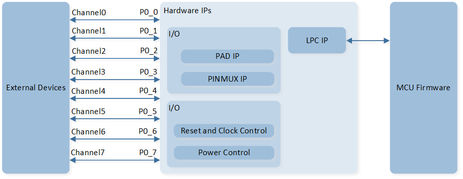
System Block Diagram of LPC
External Input Channels
Configure LPC external input channels during initialization via LPC_InitTypeDef::LPC_Channel.
RTL87x3D supports 8 external input channels: external channel 0, 1, 2, 3, 4, 5, 6, and 7 correspond to pin P0_0, P0_1, P0_2, P0_3, P0_4, P0_5, P0_6, and P0_7 respectively.
RTL87x3E and RTL87x3EP support 4 external input channels: external channel 0, 1, 2, and 3 correspond to pin P0_0, P0_1, P0_2, and P0_3 respectively.
Voltage Detection
The input voltage is compared with the internal reference voltage of LPC to trigger voltage detection interrupt, higher or lower than threshold voltage.
Configure LPC trigger edge during initialization via LPC_InitTypeDef::LPC_Edge.
Configure LPC voltage threshold during initialization via LPC_InitTypeDef::LPC_Threshold.
Power Manager
The LPC peripheral is located in the AON domain, it will be powered off in ship mode.
The system can be awakened from DLPS/power down mode when the voltage detection trigger conditions are satisfied.
Call RTC_SystemWakeupConfig() function to set LPC wake-up functionality.