TIMER and PWM
Sample List
This chapter introduces the details of the TIMER and PWM sample code. The SDK provides the following samples for the TIMER and PWM peripheral.
Functional Overview
The TIMER consists of a 32-bit automatic load counter. Each TIMER is completely independent and does not share any resources. They can operate synchronously together. The TIMER can operate in two modes: user-defined count mode and free-running mode. In user-defined count mode, the TIMER counts down from the value set by the user. In free-running mode, the TIMER counts down from 0xffffffff. When the TIMER counter is enabled after being reset or disabled, the TIMER counts down from its initial value, and when it reaches 0, an interrupt is triggered.
Feature List
2 modes (Free-run/User define).
Support PWM output function.
32-bit decrement counter.
Timeout interrupt.
Complementary PWM output & dead zone (Only TIMER 2/TIMER 3).
Independent input clock divider 1/2, 1/4, 1/8, 1/40.
Note
RTL87x3D supports up to 16 TIMER, 12 of which can be used for application.
RTL87x3E supports up to 8 TIMER, 5 of which can be used for application.
RTL87x3EP supports up to 12 TIMER, 9 of which can be used for application, but only 5 of which can be used for the PWM function.
TIMER 0 and TIMER 1 of RTL87x3D, RTL87x3E and RTL87x3EP are reserved for low stack.
TIMER 7 of RTL87x3D, RTL87x3E and RTL87x3EP is reserved for log time stamp.
Block Diagram
Here is the overall IPs block diagram for TIMER IP¹, which including ‘PAD/PINMUX’ for IO function configuration, ‘TIMER IP’ for TIMER protocol, ‘DMAC IP’ for GDMA access.
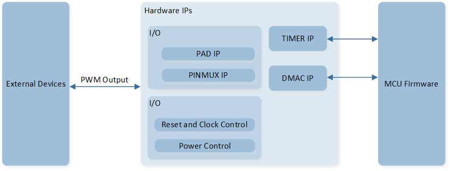
System Block Diagram of TIMER
TIMER Mode
Call hw_timer_create() to create the timer according to the specified parameters. Call hw_timer_start() to start the specified timer.
Configure the third parameter of hw_timer_create() to set TIMER to a periodic timer or a one-shot timer.
When the third parameter of hw_timer_create() is configured as true, when the count reaches 0, the TIMER timeout interrupt is triggered and the callback function registered to the TIMER module is executed, and the counter reloads the initial value and continues to count down.
When the third parameter of hw_timer_create() is configured as false, when the count reaches 0, the TIMER timeout interrupt is triggered and the callback function registered to the TIMER module is executed, and the TIMER stops counting.
PWM Mode
Call pwm_create() to create the PWM according to the specified parameters. Call pwm_start() to start the specified PWM to output high level and low level.
When PWM is enabled, the PWM will load the set counter values to output high and low levels for the specified duration. The counter value for the high level is configured through the second parameter of pwm_create(), and the counter value for the low level is configured through the parameter the third parameter of pwm_create().
User can call pwm_change_duty_and_frequency() to change high level count and low level count.

PWM Waveform
Complementary Output and Dead Zone
Only TIMER 2 and TIMER 3 support PWM complementary output and dead-time features. In the initialization, configure the fourth parameter of pwm_create() to true to activate this feature. Once this feature is enabled, the PWM output will be divided into two channels, namely PWM_P and PWM_N.
Call pwm_config() to configure the dead zone parameters.
The calculation formula for the dead zone time is: dead zone time = dead zone size * dead zone clock period. The clock source for the dead zone time is 32kHz.
The dead zone size is set via _T_HW_TIMER_PWM::pwm_deadzone_size.
Power Manager
The TIMER peripheral is located in the core domain and will be powered off in low power mode.
TIMER peripheral store/restore will be automatically performed based on whether the TIMER clock is active.
Users can call the API io_dlps_register() to initialize TIMER peripheral store/restore and do not need to worry about TIMER peripheral requiring specific handling.
The system is not allowed to enter low power mode when PWM is enabled.
By default, when the TIMER is activated, the system is allowed to enter low power mode when the TIMER timing time exceeds 30ms.
When the system enters low power mode, the hw_tim module will perform time compensation to ensure that the system can be woken up and the hw_tim callback function can be executed normally after the timing ends.
Users can call the API hw_timer_lpm_set() to configure whether to allow the system to enter low power mode when the TIMER is activated.