UART
Sample List
This chapter introduces the details of the UART sample code. The SDK provides the following samples for the UART peripheral.
Functional Overview
UART provides a flexible method for full-duplex data exchange with external devices. The UART utilizes a fractional baud rate generator to provide a wide range of baud rate options. It supports half-duplex single-wire communication. UART can also be used with GDMA to achieve high-speed data communication.
Feature List
Support 1-bit or 2-bit stop bit.
Support 7-bit or 8-bit data format.
Support odd or even parity.
Support hardware flow control.
Programmable baud rate.
Support GDMA.
Support one-wire UART.
Block Diagram
Here is the overall IPs block diagram for UART IP¹, which including ‘PAD/PINMUX’ for IO function configuration, ‘UART IP’ for UART protocol, ‘DMAC IP’ for GDMA access.
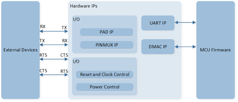
System Block Diagram of UART
Transfer Protocol
Data Format
Data format is configured by UART_InitTypeDef::wordLen.
The schematic diagram of the 7-bit data format is shown in the following figure.
Set UART_InitTypeDef::wordLen to UART_WROD_LENGTH_7BIT to set the 7-bit data format.
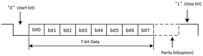
Schematic Diagram of 7-bit Data Format
The schematic diagram of the 8-bit data format is shown in the following figure.
Set UART_InitTypeDef::wordLen to UART_WROD_LENGTH_8BIT to set the 8-bit data format.
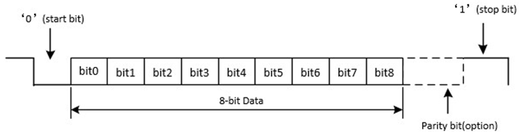
Schematic Diagram of 8-bit Data Format
Parity Check
Parity check is configured by UART_InitTypeDef::parity.
-
Odd Parity
Odd parity means that the number of ‘1’ in the data bits and check bit is odd. When the number of ‘1’ in the data bits is odd, the check bit is ‘0’; otherwise, it is ‘1’. Set
UART_InitTypeDef::paritytoUART_PARITY_ODDto set the odd parity. -
Even Parity
Even parity means that the number of ‘1’ in the data bits and check bit is even. When the number of ‘1’ in the data bits is even, the check bit is ‘0’; otherwise, it is ‘1’. Set
UART_InitTypeDef::paritytoUART_PARITY_EVENto set the even parity.
Hardware Flow Control
Hardware flow control function is configured by UART_InitTypeDef::autoFlowCtrl. The schematic diagram of hardware flow control is shown in the following figure.
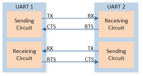
Schematic Diagram of Hardware Flow Control
-
RTS Flow Control
When the UART receiver is ready to accept new data, RTS becomes valid, and the low level is valid. When the number of data in the RX FIFO reaches the set RX trigger level, RTS becomes invalid (high level is invalid), thereby indicating that it is desired to stop data transmission at the end of the current frame.
-
CTS Flow Control
The transmitter checks the CTS before sending the next frame. If CTS is valid (low level is valid), the next data is sent; otherwise, the next frame data is not sent. If the CTS becomes invalid (high level is invalid) during transmission, the transmission is stopped after the current transmission is completed.
Baud Rate
Set the baud rate by configuring the parameters UART_InitTypeDef::div, UART_InitTypeDef::ovsr, and UART_InitTypeDef::ovsr_adj. UART baud rate table is shown below.
Baud Rate |
|||
|---|---|---|---|
1200 |
2589 |
7 |
0x7F7 |
9600 |
271 |
10 |
0x24A |
14400 |
271 |
5 |
0x222 |
19200 |
123 |
11 |
0x6FF |
28800 |
82 |
11 |
0x6FF |
38400 |
85 |
7 |
0x222 |
57600 |
41 |
11 |
0x6FF |
76800 |
35 |
9 |
0x7EF |
115200 |
20 |
12 |
0x252 |
128000 |
25 |
7 |
0x555 |
153600 |
15 |
12 |
0x252 |
230400 |
10 |
12 |
0x252 |
460800 |
5 |
12 |
0x252 |
500000 |
8 |
5 |
0 |
921600 |
3 |
9 |
0x2AA |
1000000 |
4 |
5 |
0 |
1382400 |
2 |
9 |
0x2AA |
1444000 |
2 |
8 |
0x5F7 |
1500000 |
2 |
8 |
0x492 |
1843200 |
2 |
5 |
0x3F7 |
2000000 |
2 |
5 |
0 |
2100000 |
2 |
14 |
0x400 |
2764800 |
1 |
9 |
0x2AA |
3000000 |
1 |
8 |
0x492 |
Power Manager
The UART peripheral is located in the core domain and will be powered off in low power mode.
UART peripheral store/restore will be automatically performed based on whether the UART clock is active.
Users can call the API io_dlps_register() to initialize UART peripheral store/restore and do not need to worry about UART peripheral requiring specific handling.