UART RX Data in Interrupt Mode
This sample code guide is designed to help users easily and comprehensively understand UART sample. This sample demonstrates how UART receives data in interrupt mode. This sample code demonstrates the communication between chip and PC terminal. PC terminal transmits some data to chip and then chip returns the same data received plus string \r\n to PC terminal.
Requirements
For hardware requirements, please refer to the Requirements.
In addition, it is necessary to install serial port assistant tools such as PuTTY or UartAssist on the PC terminal.
Wiring
Connect P3_1 (UART TX Pin) to the RX pin of the FT232 and P3_0 (UART RX Pin) to the TX pin of the FT232.
The hardware connection of UART sample code is shown in the figure below.
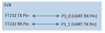
UART Sample Code Hardware Connection Diagram
Configurations
-
The following macros can be configured to modify pin definitions.
#define UART_TX_PIN P3_1#define UART_RX_PIN P3_0
-
The entry function is as follows, call this function in
main()to run this sample code. For more details, please refer to the Initialization.uart_demo();
Building and Downloading
For building and downloading, please refer to the Building and Downloading.
Experimental Verification
Preparation Phase
Start a PC terminal program like PuTTY or UartAssist and connect to the used COM port with the following UART settings:
Baud rate: 115200.
8 data bits.
1 stop bit.
No parity.
No hardware flow control.
Testing Phase
Press the Reset button on the EVB, chip starts with transmitting ### Welcome to use RealTek Bumblebee ###\r\n. Observe that the string appears on the PC terminal program.
Use PC terminal program to send data to chip. After the chip receives the data, it will send the received same data plus string \r\n back to PC terminal. Observe that the string appears on the PC terminal program.
Code Overview
This section introduces the code and process description for initialization and corresponding function implementation in the sample.
Source Code Directory
For project directory, please refer to Source Code Directory.
Source code directory:
sdk\src\sample\io_demo\uart\interrupt\uart_demo.c.
Initialization
The initialization flow for peripherals can refer to Initialization Flow.
UART initialization flow is shown in the following figure.
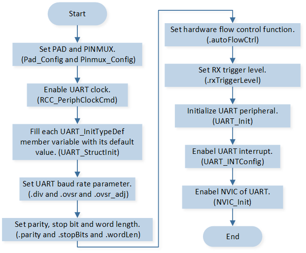
UART Initialization Flow Chart
-
Call
Pad_Config()andPinmux_Config()to initialize the pin.static void board_uart_init(void) { Pad_Config(UART_TX_PIN, PAD_PINMUX_MODE, PAD_IS_PWRON, PAD_PULL_NONE, PAD_OUT_DISABLE, PAD_OUT_LOW); Pad_Config(UART_RX_PIN, PAD_PINMUX_MODE, PAD_IS_PWRON, PAD_PULL_UP, PAD_OUT_DISABLE, PAD_OUT_LOW); Pinmux_Config(UART_TX_PIN, UART0_TX); Pinmux_Config(UART_RX_PIN, UART0_RX); }
Call
RCC_PeriphClockCmd()to enable the UART clock and function.-
Initialize the UART peripheral:
Define the
UART_InitTypeDeftypeuartInitStruct, and callUART_StructInit()to pre-filluartInitStructwith default values.Modify the
uartInitStructparameters as needed. The UART initialization parameter configuration is shown in the table below.Call
UART_Init()to initialize the UART peripheral.
UART Initialization Parameters UART Hardware Parameters
Setting in the
uartInitStructUART
div
20
ovsr
12
ovsr_adj
0x252
Parity Check
Stop Bit
Data Format
Hardware Flow Control
RX Trigger Level
Call
UART_INTConfig()to enable received data available interruptUART_INT_RD_AVAand RX idle timeout interruptUART_INT_IDLEand receiver line status interruptUART_INT_LINE_STS.Call
NVIC_Init()to enable NVIC of UART.
Functional Implementation
Send Data
Transmit ### Welcome to use RealTek Bumblebee ###\r\n to the PC terminal:
Call
UART_SendData()to continuously write data to the TX FIFO. The number of data continuously written to the TX FIFO must not exceed the size of the TX FIFO.Call
UART_GetFlagState()to checkUART_FLAG_THR_TSR_EMPTYflag state and wait for both TX FIFO and TX shift register to be empty.Repeat the above process to send all data to TX FIFO in batches.
Interrupt Handle
After the PC terminal sends a string, the chip will trigger UART interrupts. UART interrupt handle flow is shown in the following figure.
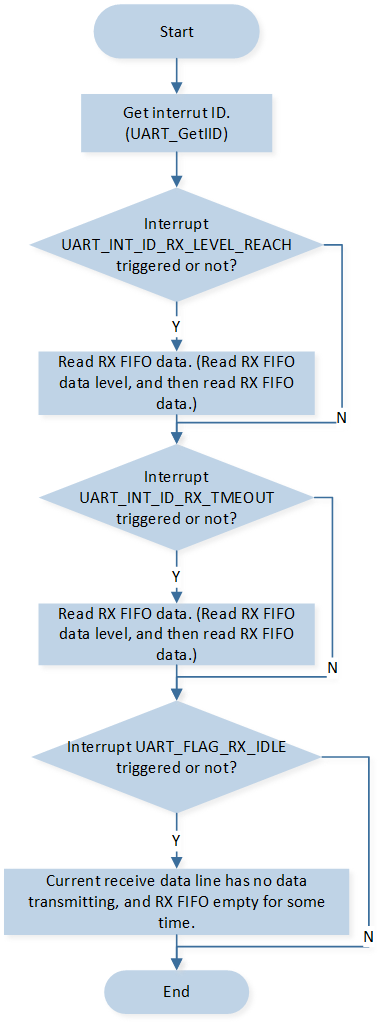
UART Interrupt Handle Flow
Call
UART_GetIID()to get the interrupt ID.-
If the RX FIFO level reached the RX trigger level set in
UART_InitTypeDef::rxTriggerLevel,UART_INT_ID_RX_LEVEL_REACHinterrupt first is triggered first:Call
UART_GetRxFIFOLen()to get the data length in RX FIFO.Call
UART_ReceiveData()to receive data from RX FIFO.
-
There’s at least 1 UART data in the RX FIFO but no character has been input to the RX FIFO or read from it for the last time of 4 characters.
UART_INT_ID_RX_TMEOUTinterrupt is triggered:Call
UART_GetRxFIFOLen()to get the data length in RX FIFO.Call
UART_ReceiveData()to receive data from RX FIFO.
-
If No data is received in RX idle timeout time after the RX FIFO is empty (data is received before), the
UART_FLAG_RX_IDLEinterrupt is triggered:Call
UART_GetFlagState()to checkUART_FLAG_RX_IDLEinterrupt flag state.Call
UART_INTConfig()to disableUART_INT_IDLEinterrupt.Send a message to the task, and after the task receives the message, it will return the same data received plus string \r\n to PC terminal.
Call
UART_INTConfig()to enableUART_INT_IDLEinterrupt.
-
When parity error or frame error or break error or overrun error occurs,
UART_INT_ID_LINE_STATUSinterrupt is triggered:Call
UART_GetLineStatus()to get line status.