SLEEP LED
Sample List
This chapter introduces the details of the SLEEP LED sample code. The SDK provides the following samples for the SLEEP LED peripheral.
Functional Overview
SLEEP LED is used to control LED to make the effect of blinking light or breathing light.
Feature List
Support three channels.
Support blink mode and breathe mode.
32KHz clock source.
3 periods per channel in blink mode.
8 phases per channel in breathe mode.
Support output level setting high or low in idle state.
Support reverse output function.
Support period bypass in blink mode and phase bypass in breathe mode.
Block Diagram
Here is the overall IPs block diagram for SLEEP LED IP¹, which including ‘PAD/PINMUX’ for IO function configuration, ‘SLEEP LED IP’ for SLEEP LED protocol.
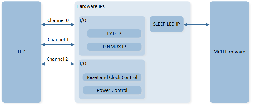
System Block Diagram of SLEEP LED
Blink Mode
In blink mode, one channel is divided into three periods. As shown in the following figure, it is executed sequentially from period0, and after the end of period2, it goes back to period0 to continue the loop execution.
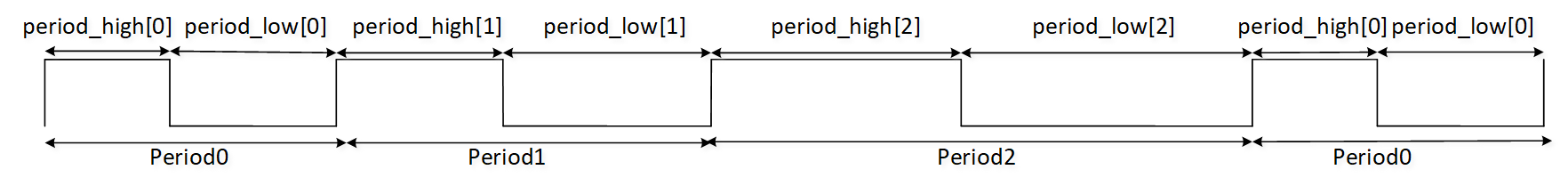
Schematic Diagram of SLEEP LED Blink Mode
Note
period_timetick =
SLEEP_LED_InitTypeDef::prescale/ 32000Period high level time =
SLEEP_LED_InitTypeDef::period_high* period_timetickPeriod low level time =
SLEEP_LED_InitTypeDef::period_low* period_timetickIf period_high[x] (x = 0, 1, 2) or period_low[x] (x = 0, 1, 2) is 0, this and subsequent periods are bypassed. For example, if period_high[2] is 0, period2 is bypassed, it is executed sequentially from period0, and after the end of period1, it goes to period0 to continue the loop execution.
Breathe Mode
In breathe mode, one channel is divided into eight phases. As shown in the following figure, it is executed sequentially from phase0, and after the end of phase7, it goes to phase0 to continue the loop execution.
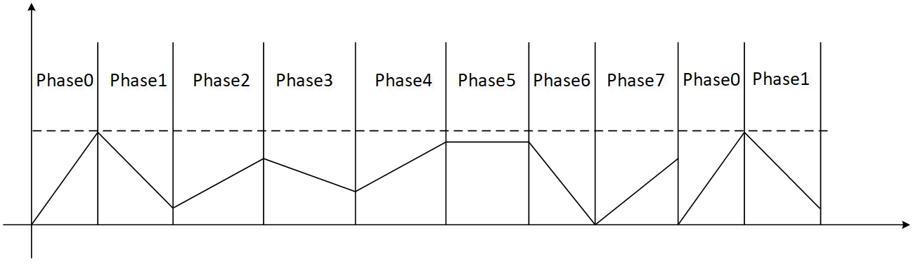
Schematic Diagram of SLEEP LED Breathe Mode
Note
phase_timetick =
SLEEP_LED_InitTypeDef::prescale/ 32000SLEEP_LED_InitTypeDef::phase_uptate_rate: duty update time = (SLEEP_LED_InitTypeDef::phase_uptate_rate+ 1) * phase_timetickSLEEP_LED_InitTypeDef::phase_phase_tick: The duration of the whole phase. phase output time =SLEEP_LED_InitTypeDef::phase_phase_tick* phase_timetickSLEEP_LED_InitTypeDef::phase_initial_duty: initial high level time =SLEEP_LED_InitTypeDef::phase_initial_duty/ 32000SLEEP_LED_InitTypeDef::phase_increase_duty: The direction of each change of duty. 1: increase duty. 0: decrease duty.SLEEP_LED_InitTypeDef::phase_duty_step: duty step time =SLEEP_LED_InitTypeDef::phase_duty_step/ 32000After high level time increases to phase_timetick, it remains at phase_timetick.
After high level time decreases to 0, it remains at 0.
Low level time = phase_timetick - high level time
If phase_phase_tick[x] (x = 0, 1, 2, …, 7) is 0, this and subsequent phases are bypassed. For example, if phase_phase_tick[6] is 0, phase6 and phase7 are bypassed, it is executed sequentially from phase0, and after the end of phase5, it goes to phase0 to continue the loop execution.
Idle State
Call the SleepLed_SetIdleMode() to set whether the channel outputs a high level or low level after the SLEEP LED is disabled.
Reverse Output Function
Each channel of SLEEP LED supports the reverse function. After the reverse function is enabled, the original waveform is reversed and output, the actual waveform is opposite to the set value.
This function is configured by SLEEP_LED_InitTypeDef::polarity.
Power Manager
The SLEEP LED peripheral of RTL87x3E is located in the PON domain, it will be powered off in power down mode and ship mode. The SLEEP LED peripheral of RTL87x3D is located in the AON domain, it will be powered off in ship mode.
Troubleshooting
LED Blink Issue When CPU Reboots
If a default pull-up pin (P1_0/P1_1/P2_0/P3_0/P3_1) is set as a high active LED, or any other pull-down pin is set as a low active LED, it will blink when CPU reboots.