PINMUX and PAD
Functional Overview
PINMUX is an abbreviation for pin multiplexing. Because the SoC has a limited number of pins, pin multiplexing allows the SoC to use the limited pins for various functions, such as SPI, I2C, and GPIO.
PAD is used to control the behavior of a pin, such as pull-up or pull-down, output high or low level, and wake-up functions.
As shown in the figure below. The PINMUX circuit and IO modules are in the core domain and will be powered down during low power mode, so they cannot work during low power mode. The PAD circuit is in the AON domain and will not be powered down during low power mode, so the PAD can work normally during low power mode. The PAD is mainly used to maintain the pin output state or wake up the system in low power mode.
The PAD can be configured as PINMUX mode and software mode. Only when the PAD is set to PINMUX mode, can this pin be connected to the core domain to achieve pin multiplexing.
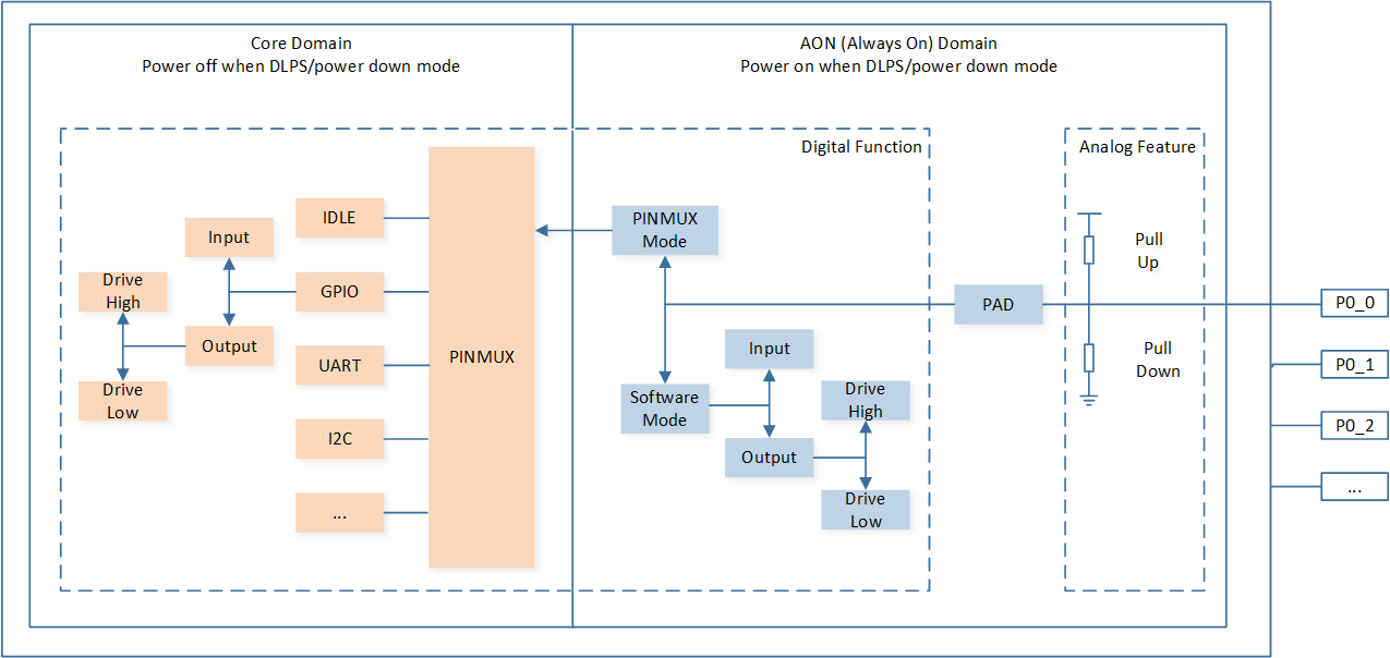
Schematic Diagram of PINMUX and PAD Circuit
Feature List
Two operating modes: PINMUX mode and software mode.
Configurable pin pull-up or pull-down resistors.
Configurable pin independently output high or low level in software mode.
Keep power during DLPS/power down mode, powered off in ship mode.
Wake up the system from DLPS and power down mode from high or low triggers on all the pins.
Block Diagram
Here is the overall IPs block diagram for PINMUX and PAD IP¹, which including ‘PAD/PINMUX’ for IO function configuration.
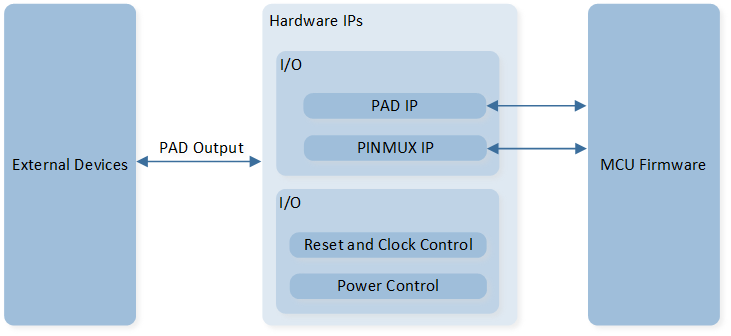
System Block Diagram of PINMUX and PAD
Hybrid PAD Usage
The hybrid PAD can be configured in digital mode or analog mode. Configure the mode of the hybrid PAD by calling Pad_AnalogMode() function.
/* Configure MIC1_P as analog mode */
Pad_AnalogMode(MIC1_P, PAD_ANALOG_MODE);
When the hybrid PAD is configured in digital mode (GPIO, I2C, etc), the AVCCDRV always on option needs to be configured as Always active on the MCUConfig Tool.
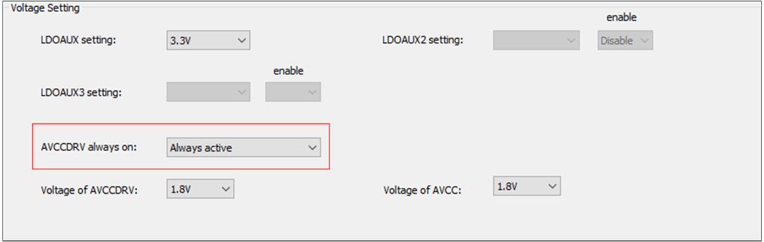
Set AVCCDRV Always On Option
Note
RTL87x3D hybrid PAD:
LOUT_N,P_UART,ROUT_N,ROUT_P,MIC1_N,MIC1_P,MIC2_N,MIC2_P,MIC3_N,MIC3_P,MIC4_N,MIC4_P,MIC5_N,MIC5_P,MIC6_N,MIC6_P,AUX_R,AUX_L,MICBIAS.RTL87x3E hybrid PAD:
AUX_R,AUX_L,MIC1_P,MIC1_N,MIC2_P,MIC2_N,MICBIAS,LOUT_P,LOUT_N,ROUT_P,ROUT_N,MIC3_P,MIC3_N.RTL87x3EP hybrid PAD:
DAOUT_P,DAOUT_N,MIC1_P,MIC1_N,MIC2_P,MIC2_N,MICBIAS.
Power Manager
The PINMUX circuit is in the core domain and will be powered down during low power mode, so they cannot work during low power mode.
The PAD circuit is in the AON domain and will not be powered down during low power mode, so the PAD can work normally during low power mode.
The PAD can be used to wake up the system from DLPS/power down mode. Call the API System_WakeUpPinEnable() to enable the wake up function of PAD.
For detailed descriptions, please refer to Use Wakeup Pin and PAD (AON).