ADC
Sample List
This chapter introduces the details of the ADC sample code. The SDK provides the following samples for the ADC peripheral.
Functional Overview
Feature List
12-bit resolution.
Support external channels, and VBAT and VADPIN internal channels.
Two external channel input modes: bypass mode and divide mode.
Support external single-ended mode.
Two work modes: one shot mode and continuous mode.
16 index schedule table.
TIMER7 triggers ADC one shot mode sampling.
32 depth FIFO for continuous mode.
Support hardware average function.
Number of hardware average sample: max 256.
GDMA supported (Continuous Mode).
Block Diagram
Here is the overall IPs block diagram for ADC IP¹, which including ‘PAD/PINMUX’ for IO function configuration, ‘ADC IP’ for ADC protocol, ‘DMAC IP’ for GDMA access.
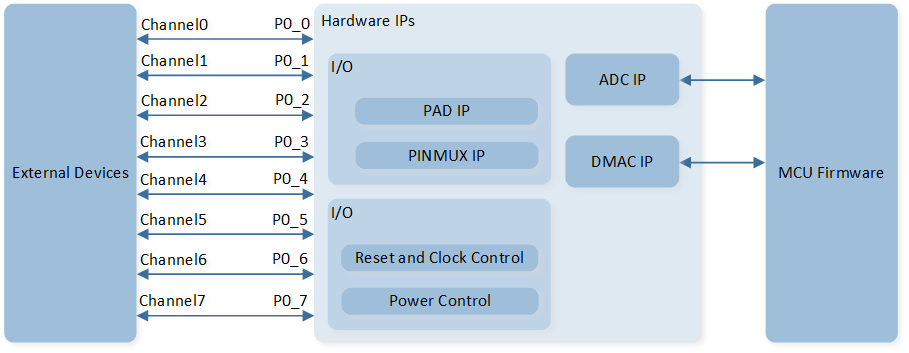
System Block Diagram of ADC
External channels
RTL87x3D supports 8 external channels: external channel 0, 1, 2, 3, 4, 5, 6, and 7 correspond to pin P0_0, P0_1, P0_2, P0_3, P0_4, P0_5, P0_6, and P0_7.
RTL87x3E and RTL87x3EP support 4 external channels: external channel 0, 1, 2, and 3 correspond to pin P0_0, P0_1, P0_2, and P0_3.
Channel Mode
-
Single-Ended Mode
Single-Ended mode occupies one channel and uses only one pin for sampling. Call
EXT_SINGLE_ENDEDset the corresponding ADC channel to the schedule tableADC_InitTypeDef::schIndex. -
Internal VBAT and Internal VADPIN Modes
Internal VBAT mode is used to measure VBAT voltage. Internal VADPIN mode is used to measure VADP voltage. Call
INTERNAL_VBAT_MODEset the VBAT channel to the schedule tableADC_InitTypeDef::schIndex. CallINTERNAL_VADPIN_MODEset the VADPIN channel to the schedule tableADC_InitTypeDef::schIndex.
External Channel Input Mode
-
Bypass Mode
The input range of ADC bypass mode is 0 to 0.9V. Call
ADC_HighBypassCmd()to set corresponding channel to bypass mode. -
Divide Mode
The input range of ADC divide mode is 0 to 3.3V. The default setting is divide mode.
Work Mode
-
One Shot Mode
After ADC is enabled, only one sampling is performed. To sample again, the user needs to manually restart sampling.
The data is by default stored in the schedule table. If set
ADC_InitTypeDef::dataWriteToFifotoFunctionalState::ENABLE, data can be optionally stored in FIFO in one shot mode.Fill in
ADC_One_Shot_Modewithin theADC_Cmd()to enable ADC continuous mode sampling.It can cooperate with TIMER 7 peripheral to realize timing continuous sampling.
-
Continuous Mode
After ADC is enabled, sampling continues until ADC is disabled.
The data is stored in the ADC FIFO.
It can cooperate with GDMA continuous sampling.
Fill in
ADC_Continuous_Modewithin theADC_Cmd()to enable ADC continuous mode sampling.
Schedule Table Index
ADC has 16 schedule tables. Write the parameters in the table below into schIndex[0] ~ schIndex[15] to set channel mode and channel number.
Then set bitmap, schIndex[0] ~ schIndex[15] corresponding to bit 0 ~ bit 15 of bitmap. If the specific bit of bitmap is set to 1, it means that the schedule table corresponding to this bit is enabled. For example, if configure schIndex[0] and schIndex[1], then bitmap is
0000 0000 0011(that is,0x0003), if configure schIndex[0] and schIndex[2], then bitmap is0000 0000 0101(that is,0x0005). This bitmap parameter is configured byADC_InitTypeDef::bitmap.After ADC is enabled, ADC will sample successively according to the mode configured in the enabled schedule table.
|
Description |
|---|---|
|
Single-Ended mode, the input is external channel 0. |
|
Single-Ended mode, the input is external channel 1. |
|
Single-Ended mode, the input is external channel 2. |
|
Single-Ended mode, the input is external channel 3. |
|
Single-Ended mode, the input is external channel 4. |
|
Single-Ended mode, the input is external channel 5. |
|
Single-Ended mode, the input is external channel 6. |
|
Single-Ended mode, the input is external channel 7. |
|
Internal battery voltage detection channel. |
|
Internal adapter voltage detection channel. |
Power Manager
The ADC peripheral is located in the core domain and will be powered off in low power mode.
ADC peripheral store/restore will be automatically performed based on whether the ADC clock is active.
Users can call the API io_dlps_register() to initialize ADC peripheral store/restore and do not need to worry about ADC peripheral requiring specific handling.