ADC One Shot and Interrupt Mode
This sample code guide is designed to help users easily and comprehensively understand ADC sample. This sample demonstrates how ADC samples data by interrupt mode in one shot mode. This sample uses one shot mode of ADC peripheral to measure voltage on P0_0, P0_1, VBAT, and VADP by interrupt mode.
Requirements
For hardware requirements, please refer to the Requirements.
Wiring
Connect P0_0 and P0_1 of EVB to external DC voltage source. Input voltage of P0_0 must range from 0 to 3.3V, and input voltage of P0_1 must range from 0 to 0.9V.
Connect Lithium-ion battery to EVB.
Connect VADP to 5V of EVB.
The hardware connection of ADC sample code is shown in the figure below.
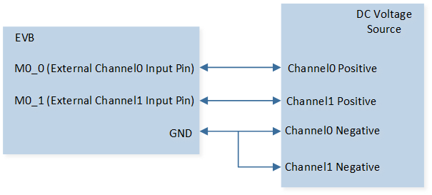
ADC Sample Code Hardware Connection Diagram
Configurations
-
The following macros can be configured to modify the sampling interval.
#define ADC_TIMER_PERIOD 1000
-
The entry function is as follows, call this function in
main()to run this sample code. For more details, please refer to the Initialization.adc_demo();
Building and Downloading
For building and downloading, please refer to the Building and Downloading.
Experimental Verification
Press the Reset button on the EVB board, ADC samples every 1000ms. Once ADC sampling is finished, the converted voltage values will be printed in Debug Analyzer.
adc_handler: res[0] xxx, res[1] xxx, res[2] xxx, res[3] xxx
Code Overview
This section introduces the code and process description for initialization and corresponding function implementation in the sample.
Note
To use the mode, please turn off Charger auto enable and Battery detection support on the MCUConfig Tool. As shown in Turn Off Charger on the MCUConfig Tool.
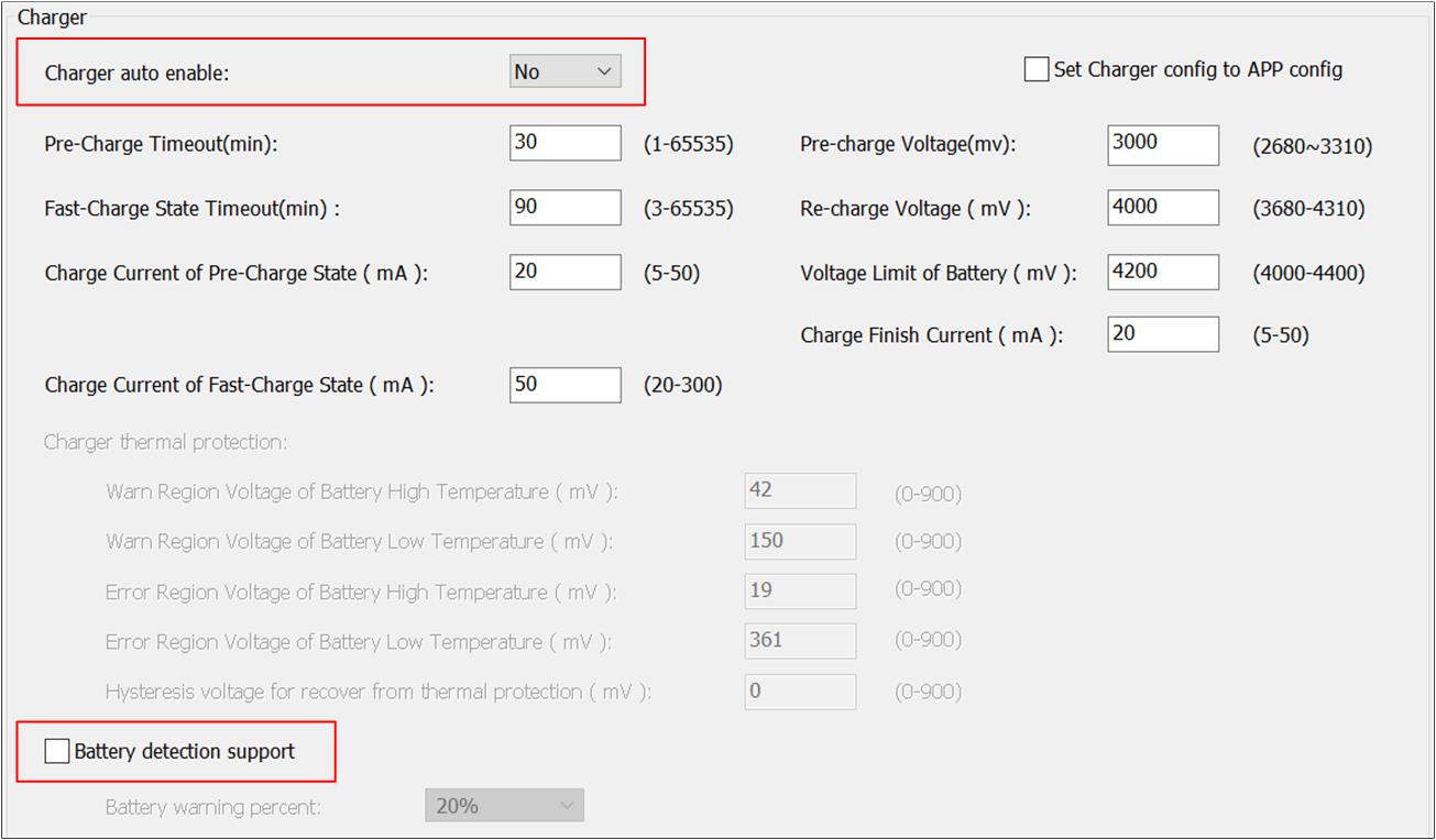
Turn Off Charger on the MCUConfig Tool
Source Code Directory
For project directory, please refer to Source Code Directory.
Source code directory:
sdk\src\sample\io_demo\adc\one-shot\adc_demo.c.
Initialization
The initialization flow for peripherals can refer to Initialization Flow.
The initialization flow of ADC sampling in one shot mode by interrupt mode is shown in the following figure.
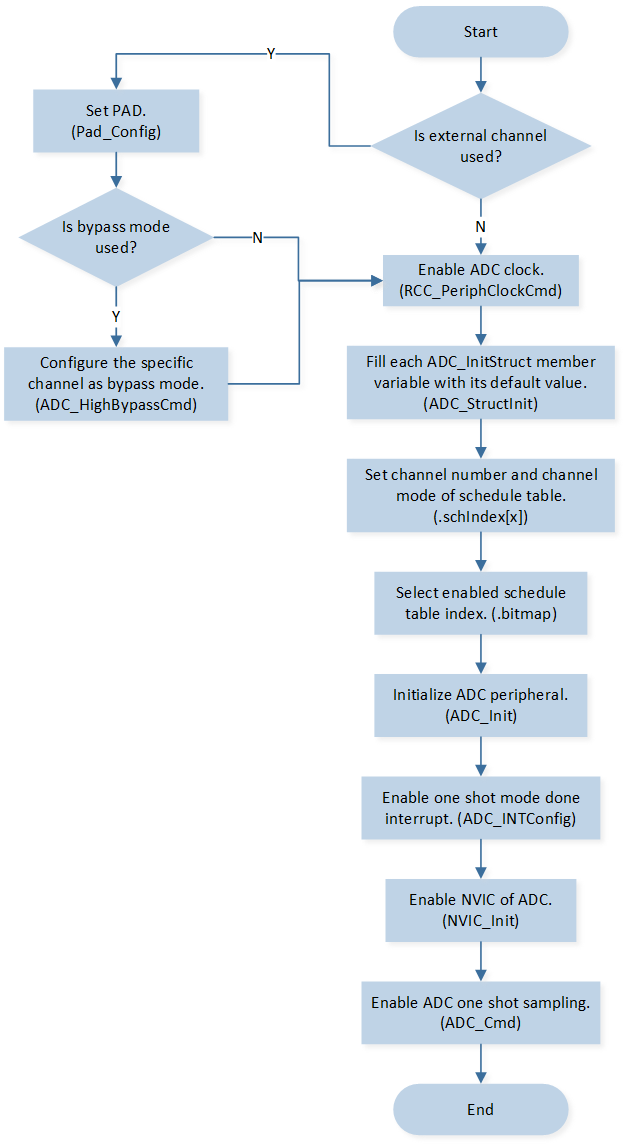
ADC One Shot Sampling by Interrupt Mode
-
Call
Pad_Config()andPinmux_Config()to initialize the pin.Pad_Config(ADC_0, PAD_SW_MODE, PAD_IS_PWRON, PAD_PULL_NONE, PAD_OUT_DISABLE, PAD_OUT_LOW); Pad_Config(ADC_1, PAD_SW_MODE, PAD_IS_PWRON, PAD_PULL_NONE, PAD_OUT_DISABLE, PAD_OUT_LOW); Pinmux_Config(ADC_0, IDLE_MODE); Pinmux_Config(ADC_1, IDLE_MODE);
Call
ADC_HighBypassCmd()to configure the specific channel as bypass mode.Call
RCC_PeriphClockCmd()to enable the ADC clock and function.-
Initialize the ADC peripheral:
Define the
ADC_InitTypeDeftypeadcInitStruct, and callADC_StructInit()to pre-filladcInitStructwith default values.Modify the
adcInitStructparameters as needed. The ADC initialization parameter configuration is shown in the table below.Call
ADC_Init()to initialize the ADC peripheral.
ADC Initialization Parameters ADC Hardware Parameters
Setting in the
adcInitStructVariablesADC
Bit Map
0x0f
Schedule Index
Index 0 is set to
EXT_SINGLE_ENDED(0).Index 1 is set to
EXT_SINGLE_ENDED(1).Index 2 is set to
INTERNAL_VBAT_MODE.Index 3 is set to
INTERNAL_VADPIN_MODE. Call
ADC_INTConfig()to enable ADC one shot mode done interrupt.Call
NVIC_Init()to enable NVIC of ADC.Call
ADC_Cmd()to enable ADC one shot sampling.
Functional Implementation
Interrupt Handle
When ADC sampling is completed, ADC one shot mode end interrupt is triggered and enters the interrupt handler. ADC interrupt handle flow is shown in the following figure.
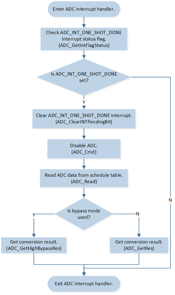
ADC Interrupt Handle Flow
Call
ADC_GetIntFlagStatus()to checkADC_INT_ONE_SHOT_DONEinterrupt status flag.Call
ADC_ClearINTPendingBit()to clearADC_INT_ONE_SHOT_DONEinterrupt.Call
ADC_Cmd()to disable ADC.Call
ADC_Read()to read ADC raw data from schedule table.Call
ADC_GetRes()andADC_GetHighBypassRes()to get conversion result.