QDEC
Sample List
This chapter introduces the details of the QDEC sample code. The SDK provides the following samples for the QDEC peripheral.
Functional Overview
As shown in the following figure, QDEC is used to detect the motion state of the rotation-sensing device. When the rotating device moves, it will output two quadrature signals PHA and PHB. QDEC judges the direction of rotation by detecting the phase change of PHA and PHB.
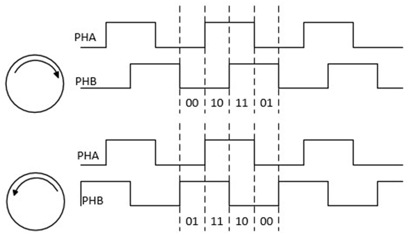
Schematic Diagram of Two Quadrature Signals of QDEC
Feature List
2 input quadrature decoder
Support 3 independent axes (X, Y, Z).
Support hardware debounce: debounce time for each axis can be set independently.
Support initial phase setting.
Support illegal phase change detection.
16-bit phase change counter.
Block Diagram
Here is the overall IPs block diagram for QDEC IP¹, which including ‘PAD/PINMUX’ for IO function configuration, ‘QDEC IP’ for QDEC protocol.
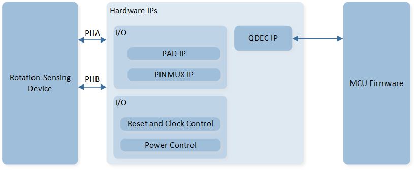
System Block Diagram of QDEC
Direction Judgment and Counting Method
PHA and PHB are combined into a 2-bit number. PHA is the high bit, and PHB is the low bit.
The phases are divided into four types: 00, 01, 11, and 10.
As shown in the following figure, changes in the order of 00, 01, 11, and 10 are defined as positive. When the counter scale is set to 0, the counter will increase by one when the phase changes once. When the counter scale is set to 1, the counter will increase by one when the phase changes twice.
Changes in the order of 00, 10, 11, and 01 are defined as negative. When the counter scale is set to 0, the counter will decrease by one when the phase changes once. When the counter scale is set to 1, the counter will decrease by one when the phase changes twice.
PHA and PHB should only have one signal change at a time. If both signals change at the same time, the state is considered wrong. When this error state occurs, the counter does not count. Illegal interrupts can be turned on to detect this error condition.
When the counter value is 0x0000, the device rotates in reverse (counter value decreases by 1), causing the counter to underflow and become 0xFFFF, while setting
QDEC_FLAG_UNDERFLOW_XorQDEC_FLAG_UNDERFLOW_YorQDEC_FLAG_UNDERFLOW_Zflag to 1.When the counter value is 0xFFFF, the device rotates forward (counter value increases by 1), causing the counter to overflow and become 0x0000, while setting
QDEC_FLAG_OVERFLOW_XorQDEC_FLAG_OVERFLOW_YorQDEC_FLAG_OVERFLOW_Zflag to 1.
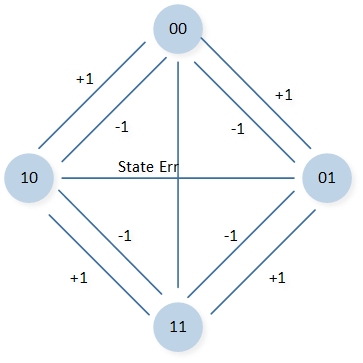
Schematic Diagram of QDEC Direction Judgment
Power Manager
The QDEC peripheral is located in the core domain and will be powered off in low power mode.
QDEC peripheral store/restore will be automatically performed based on whether the QDEC clock is active.
Users can call the API io_dlps_register() to initialize QDEC peripheral store/restore and do not need to worry about QDEC peripheral requiring specific handling.