QDEC Phase Detection
This sample code guide is designed to help users easily and comprehensively understand QDEC sample. This sample uses QDEC to detect the direction and count of wheel turns.
Requirements
For hardware requirements, please refer to the Requirements.
Wiring
Connect P1_0 to the PHA of the wheel, connect P1_1 to the PHB of the wheel.
The hardware connection of QDEC sample code is shown in the figure below.
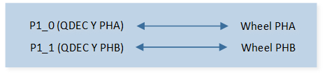
QDEC Sample Code Hardware Connection Diagram
Configurations
-
The following macros can be configured to modify pin definitions.
#define QDEC_Y_PHA_PIN P1_0#define QDEC_Y_PHB_PIN P1_1
-
The entry function is as follows, call this function in
main()to run this sample code. For more details, please refer to the Initialization.qdec_demo();
Building and Downloading
For building and downloading, please refer to the Building and Downloading.
Experimental Verification
Preparation Phase
Press the Reset button on the EVB, when QDEC Y-axis detects new data, it triggers an interrupt and prints the interrupt message, the direction, and the number of scroll wheel rolls.
qdec_handler: dir xx, y_axis xx
Code Overview
This section introduces the code and process description for initialization and corresponding function implementation in the sample.
Source Code Directory
For project directory, please refer to Source Code Directory.
Source code directory:
sdk\src\sample\io_demo\qdec\qdec_demo.c.
Initialization
The initialization flow for peripherals can refer to Initialization Flow.
QDEC initialization flow is shown in the following figure.
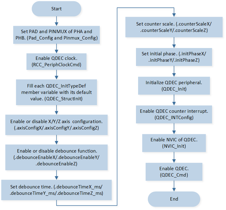
QDEC Initialization Flow Chart
-
Call
Pad_Config()andPinmux_Config()to initialize the pin.static void board_qdec_init(void) { /* Qdecoder pad config */ Pad_Config(QDEC_Y_PHA_PIN, PAD_PINMUX_MODE, PAD_IS_PWRON, PAD_PULL_UP, PAD_OUT_DISABLE, PAD_OUT_LOW); Pad_Config(QDEC_Y_PHB_PIN, PAD_PINMUX_MODE, PAD_IS_PWRON, PAD_PULL_UP, PAD_OUT_DISABLE, PAD_OUT_LOW); /* Qdecoder pinmux config */ Pinmux_Config(QDEC_Y_PHA_PIN, QDEC_PHASE_A_Y); Pinmux_Config(QDEC_Y_PHB_PIN, QDEC_PHASE_B_Y); }
Call
RCC_PeriphClockCmd()to enable the QDEC clock and function.-
Initialize the QDEC peripheral:
Define the
QDEC_InitTypeDeftypeqdecInitStruct, and callQDEC_StructInit()to pre-fillqdecInitStructwith default values.Modify the
qdecInitStructparameters as needed. The QDEC initialization parameter configuration is shown in the table below.Call
QDEC_Init()to initialize the QDEC peripheral.
QDEC Initialization Parameters QDEC Hardware Parameters
Setting in the
qdecInitStructQDEC
Scan Clock
50
Debounce Clock
5
Y-axis Enable
ENABLEY-axis Debounce Enable
Y-axis Debounce Time
5 * 5
Call
QDEC_INTConfig()to enable the Y-axis counter interruptQDEC_Y_INT_NEW_DATA.Call
NVIC_Init()to enable NVIC of QDEC.Call
QDEC_Cmd()to enable the QDEC.
Functional Implementation
Interrupt Handle
QDEC interrupt handle flow is shown in the following figure.
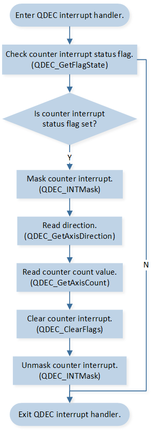
QDEC Interrupt Handle Flow Chart
when QDEC Y-axis counter value changed, it will trigger the Y-axis counter interrupt:
Call
QDEC_GetFlagState()to checkQDEC_FLAG_NEW_CT_STATUS_Yinterrupt status flag.Call
QDEC_INTMask()to maskQDEC_Y_CT_INT_MASKinterrupt.Call
QDEC_GetAxisDirection()to read direction.Call
QDEC_GetAxisCount()to read count value.Call
QDEC_ClearFlags()to clearQDEC_CLR_NEW_CT_Yinterrupt.Call
QDEC_INTMask()to unmaskQDEC_Y_CT_INT_MASKinterrupt.