IR
Sample List
This chapter introduces the details of the IR sample code. The SDK provides the following samples for the IR peripheral.
Functional Overview
The IR module provides a flexible way of transmitting and receiving IR code used in remote controls. It could send IR waveform within IR carrier and received IR waveform with IR carrier.
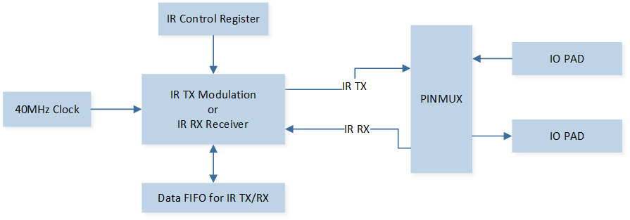
Schematic Diagram of IR Module
Feature List
-
IR Transmitter Feature:
-
IR Receiver Feature:
RX mode and TX mode cannot operate simultaneously.
Block Diagram
Here is the overall IPs block diagram for IR IP¹, which including ‘PAD/PINMUX’ for IO function configuration, ‘IR IP’ for IR protocol, ‘DMAC IP’ for GDMA access.
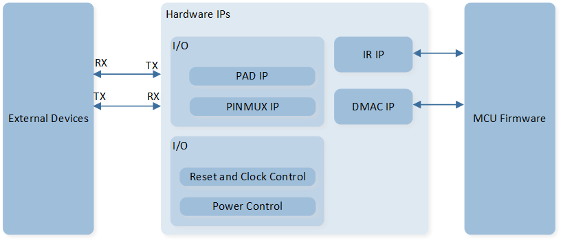
System Block Diagram of IR
IR Transmit
The schematic diagram of IR transmit is shown in the figure below.
Schematic Diagram of IR TX
The IR transmission function requires setting IR_InitTypeDef::IR_Mode to IR_MODE_TX.
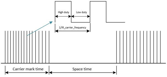
The output waveform of IR TX includes mark waveform and space waveform.
The mark waveform is the region with a carrier, while the space waveform is the region without a carrier.
By default, the mark waveform first outputs a high duty cycle, followed by a low duty cycle.
The space waveform defaults to outputting a low level.
IR TX data consists of 32 bits, and by default, the meaning of the data in the FIFO is as follows:
Data[26:0]: Represents the duration of the (Mark / Space) waveform, time = (data[26:0] + 1) * carrier_cycle.
Data[29:27]: Represents low-level compensation under the Space waveform, with a compensation time of data[29:27] * 1/8 carrier_cycle. It should be set to 0 under the Mark waveform.
Data[30]: Set to 0 to represent a normal waveform, set to 1 to represent the end waveform of TX output.
Data[31]: Set to 0 to represent the Space waveform, set to 1 to represent the Mark waveform.
IR Receive
The IR reception function requires setting IR_InitTypeDef::IR_Mode to IR_MODE_RX.
In the IR reception function, the IR_InitTypeDef::IR_Freq parameter represents the sampling frequency.
IR reception mode is divided into manual mode and automatic mode.
Manual Mode: In manual mode, call
IR_Cmd(), the counter starts, and IR begins receiving data. SetIR_InitTypeDef::IR_RxStartModetoIR_RX_MANUAL_MODEto enable manual mode.Automatic Mode: In automatic mode, after calling
IR_Cmd(), when the input waveform of the IR meets the set trigger conditions, the counter starts, and IR begins receiving data. SetIR_InitTypeDef::IR_RxStartModetoIR_RX_AUTO_MODEto enable automatic mode, and setIR_InitTypeDef::IR_RxTriggerModeto change the trigger conditions for automatic IR reception.
In IR reception mode, when reception begins, a counter starts to record the duration of high and low levels.
When the duration of the high/low level exceeds a certain value, i.e., when the counter’s count value meets the set threshold, it triggers the counter threshold interrupt IR_INT_RX_CNT_THR.
Generally, this interrupt is used to stop the IR reception function.
You can configure IR_InitTypeDef::IR_RxCntThrType to set whether the counter records high or low levels, and configure IR_InitTypeDef::IR_RxCntThr to set the counter threshold.
IR RX data consists of 32 bits, and by default, the meaning of the data in the FIFO is as follows:
Data[30:0]: Represents the RX waveform duration, time = (data[30:0] + 1) / sample_clock.
Data[31]: Represents the level of the RX waveform. 1 represents a high level, 0 represents a low level.
Power Manager
The IR peripheral is located in the core domain and will be powered off in low power mode.
IR peripheral store/restore will be automatically performed based on whether the IR clock is active.
Users can call the API io_dlps_register() to initialize IR peripheral store/restore and do not need to worry about IR peripheral requiring specific handling.