IR RX Data in Interrupt Mode
This sample code guide is designed to help users easily and comprehensively understand IR sample. This sample demonstrates how IR receives data by interrupt mode.
Requirements
For hardware requirements, please refer to the Requirements.
Wiring
Connect P0_2 to the transmitting end of the IR transceiver module.
Configurations
-
The following macros can be configured to modify pin definitions.
#define IR_RECV_PIN P0_2
-
The following macros can be configured to modify the RX threshold.
#define IR_RX_FIFO_THR_LEVEL 30
-
The entry function is as follows, call this function in
main()to run this sample code. For more details, please refer to the Initialization.ir_receive_demo();
Building and Downloading
For building and downloading, please refer to the Building and Downloading.
Experimental Verification
Send IR data to the IR transceiver module by IR remote control. The received data is stored in array IR_DataStruct.irBuf.
Code Overview
This section introduces the code and process description for initialization and corresponding function implementation in the sample.
Source Code Directory
For project directory, please refer to Source Code Directory.
Source code directory:
sdk\src\sample\io_demo\ir\receive\ir_receive_demo.c.
Initialization
The initialization flow for peripherals can refer to Initialization Flow.
IR initialization flow is shown in the following figure.
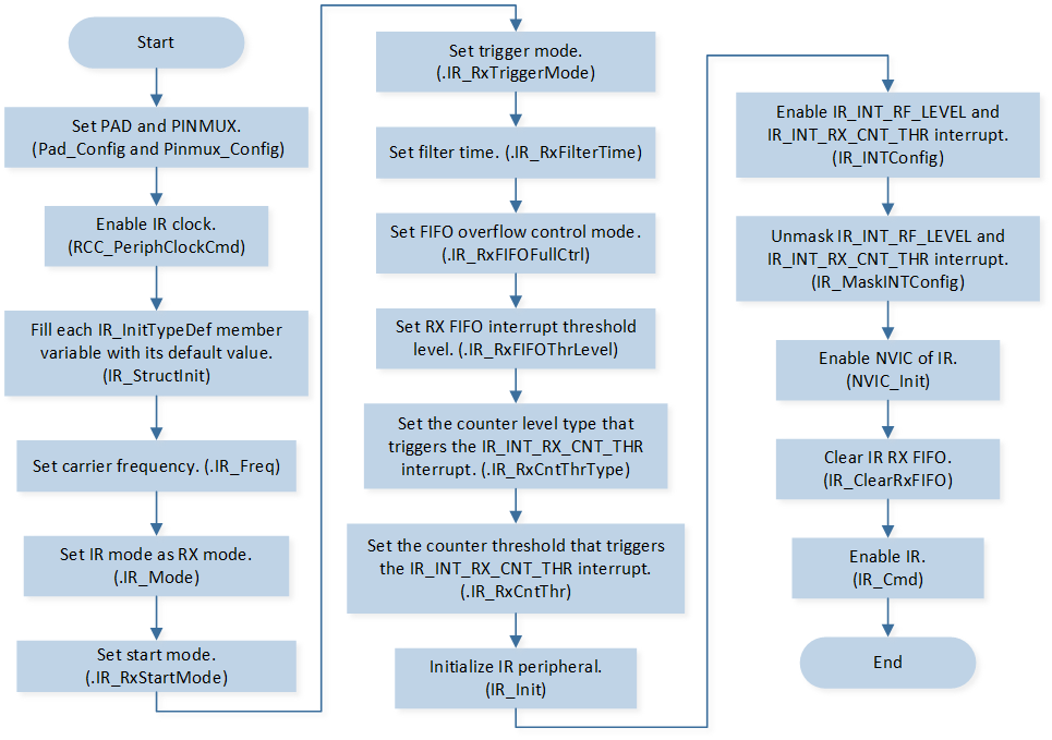
IR RX Mode Initialization Flow Chart
-
Call
Pad_Config()andPinmux_Config()to initialize the pin.static void board_ir_init(void) { Pad_Config(IR_RECV_PIN, PAD_PINMUX_MODE, PAD_IS_PWRON, PAD_PULL_NONE, PAD_OUT_DISABLE, PAD_OUT_LOW); Pinmux_Config(IR_RECV_PIN, IRDA_RX); }
Call
RCC_PeriphClockCmd()to enable the IR clock and function.-
Initialize the IR peripheral:
Define the
IR_InitTypeDeftypeIR_InitStruct, and callIR_StructInit()to pre-fillIR_InitStructwith default values.Modify the
IR_InitStructparameters as needed. The IR initialization parameter configuration is shown in the table below.Call
IR_Init()to initialize the IR peripheral.
IR Initialization Parameters IR Hardware Parameters
Setting in the
IR_InitStructIR
IR Clock Frequency
38
IR Duty Cycle
2
IR Mode
IR Rx Mode
IR RX Threshold
IR_RX_FIFO_THR_LEVELData Discard Mode
IR Rx Trigger Mode
IR RX Filter Time
IR Rx Counter Threshold Type
IR Rx Counter Threshold
0x23a
Call
IR_INTConfig()to enable the IR receive FIFO data count greater than the set receive threshold interruptIR_INT_RF_LEVELand the receive level timeout interruptIR_INT_RX_CNT_THR.Call
IR_MaskINTConfig()to unmask the IR receive FIFO data count greater than the set receive threshold interruptIR_INT_RF_LEVELand the receive level timeout interruptIR_INT_RX_CNT_THR.Call
NVIC_Init()to enable NVIC of IR.Call
IR_ClearRxFIFO()to clear IR RX FIFO.Call
IR_Cmd()to enable IR peripheral.
Functional Implementation
Interrupt Handle
IR interrupt handle flow is shown in the following figure.
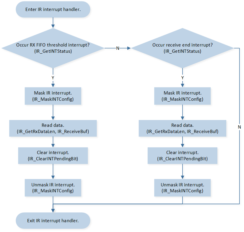
IR Interrupt Handle Flow Chart
-
When the number of data in the IR receive FIFO reaches the set receive threshold, it triggers the
IR_INT_RF_LEVELinterrupt:Call
IR_MaskINTConfig()to mask the IR receive FIFO data count greater than the set receive threshold interruptIR_INT_RF_LEVEL.Call
IR_GetRxDataLen()to get data size in RX FIFO.Call
IR_ReceiveBuf()to read data from RX FIFO.Call
IR_ClearINTPendingBit()to clear the IR receive FIFO data count greater than the set receive threshold interruptIR_INT_RF_LEVEL_CLR.Call
IR_MaskINTConfig()to unmask the IR receive FIFO data count greater than the set receive threshold interruptIR_INT_RF_LEVEL.
-
When the IR detects a low-level duration exceeding the set carrier cycle of
IR_InitTypeDef::IR_RxCntThr, it triggers theIR_INT_RX_CNT_THRinterrupt:Call
IR_MaskINTConfig()to mask the receive level timeout interruptIR_INT_RX_CNT_THR.Call
IR_GetRxDataLen()to get data size in RX FIFO.Call
IR_ReceiveBuf()to read data from RX FIFO.Call
IR_ClearINTPendingBit()to clear the receive level timeout interruptIR_INT_RX_CNT_THR_CLR.Call
IR_MaskINTConfig()to unmask the receive level timeout interruptIR_INT_RX_CNT_THR.
IR Data Decode
-
Wait for receiving the whole IR packets.
while (rx_count <= NEC_LENGTH - 5) {;};
Call
IR_NECDecodeto decode the data by the NEC protocol.