IR TX Data in Interrupt Mode
This sample code guide is designed to help users easily and comprehensively understand IR sample. The IR peripheral is used to transmit a large amount of data by interrupt mode to achieve infrared transmission functionality. A logic analyzer can be used to observe the IR transmission waveform.
Requirements
For hardware requirements, please refer to the Requirements.
Wiring
Connect P2_2 to channel 0 of the logic analyzer.
Configurations
-
The following macros can be configured to modify pin definitions.
#define IR_SEND_PIN P2_2
-
The following macros can be configured to modify the TX threshold.
#define IR_TX_FIFO_THR_LEVEL 2
-
The entry function is as follows, call this function in
main()to run this sample code. For more details, please refer to the Initialization.ir_send_interrupt_demo();
Building and Downloading
For building and downloading, please refer to the Building and Downloading.
Experimental Verification
Observe the IR TX waveform within the logic analyzer. The expected result of IR sample code is shown in the figure below.

IR Sample Code Expected Result Diagram
Code Overview
This section introduces the code and process description for initialization and corresponding function implementation in the sample.
Source Code Directory
For project directory, please refer to Source Code Directory.
Source code directory:
sdk\src\sample\io_demo\ir\send\ir_send_interrupt_demo.c.
Initialization
The initialization flow for peripherals can refer to Initialization Flow.
IR initialization flow is shown in the following figure.
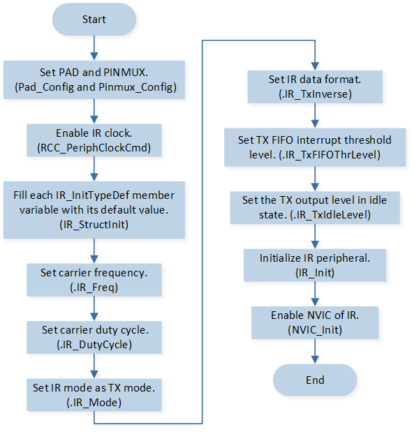
IR TX Mode Initialization Flow Chart
-
Call
Pad_Config()andPinmux_Config()to initialize the pin.static void board_ir_init(void) { Pad_Config(IR_SEND_PIN, PAD_PINMUX_MODE, PAD_IS_PWRON, PAD_PULL_NONE, PAD_OUT_DISABLE, PAD_OUT_LOW); Pinmux_Config(IR_SEND_PIN, IRDA_TX); }
Call
RCC_PeriphClockCmd()to enable the IR clock and function.-
Initialize the IR peripheral:
Define the
IR_InitTypeDeftypeIR_InitStruct, and callIR_StructInit()to pre-fillIR_InitStructwith default values.Modify the
IR_InitStructparameters as needed. The IR initialization parameter configuration is shown in the table below.Call
IR_Init()to initialize the IR peripheral.
IR Initialization Parameters IR Hardware Parameters
Setting in the
IR_InitStructIR
IR Clock Frequency
38
IR Duty Cycle
2
IR Mode
IR TX Inverse
IR TX Output Level in Idle
IR Tx Threshold
IR_TX_FIFO_THR_LEVEL Call
NVIC_Init()to enable NVIC of IR.
Functional Implementation
Send Data
IR send data operation flow is shown in the following figure.
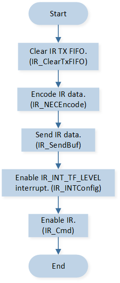
IR Send Data Operation Flow Chart
Call
IR_ClearTxFIFO()to clear IR TX FIFO.Call
IR_NECEncodeto encode the data by the NEC protocol.Call
IR_SendBuf()to continuously write data to the TX FIFO. The number of data continuously written to the TX FIFO is the size of the TX FIFO.Call
IR_INTConfig()to enable the IR transmit FIFO to reach threshold interruptIR_INT_TF_LEVEL.Call
IR_Cmd()to enable IR peripheral.
Interrupt Handle
IR interrupt handle flow is shown in the following figure.
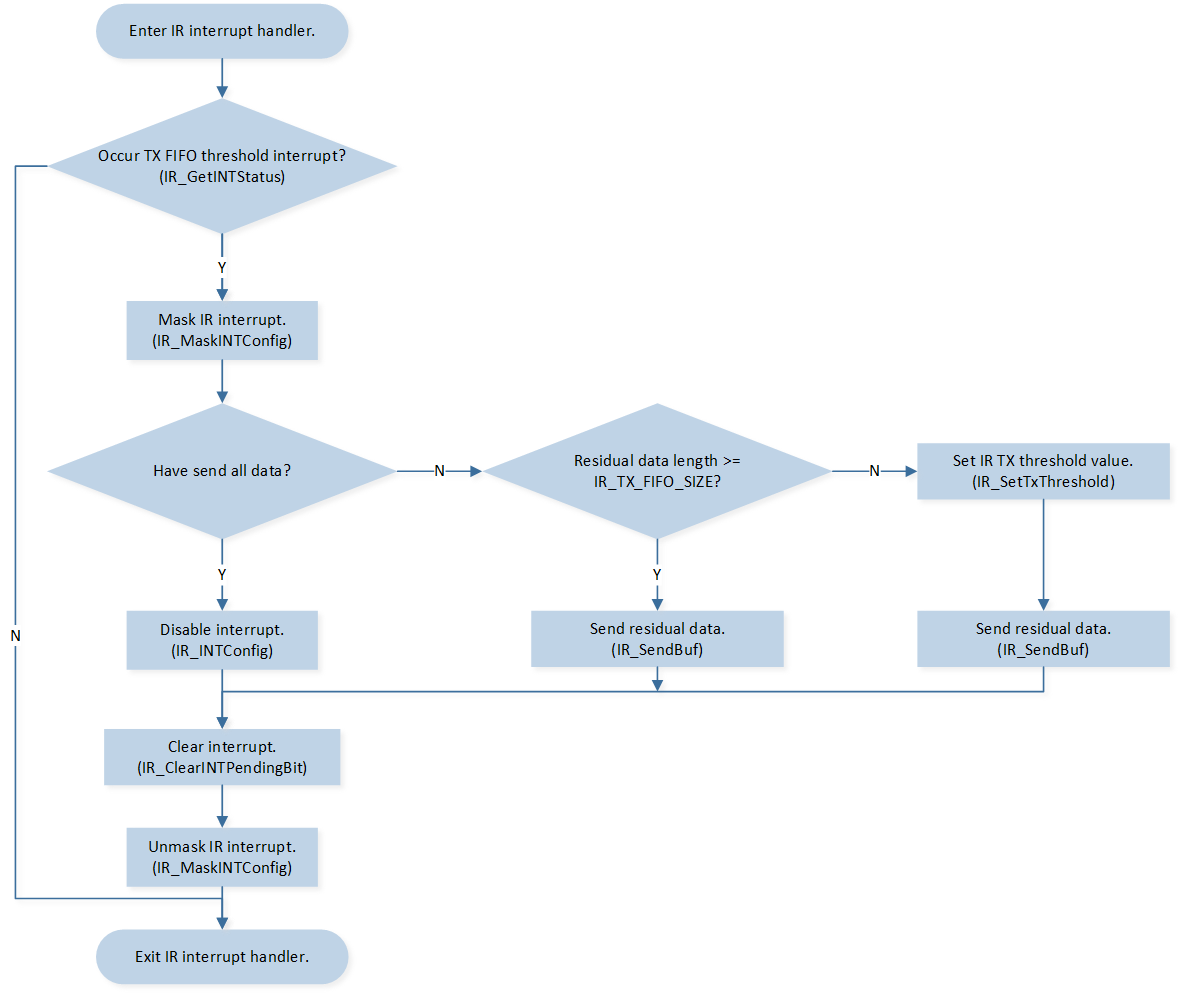
IR Interrupt Handle Flow Chart
When the number of IR transmit FIFO data is less than the set transmission threshold, it triggers the IR_INT_TF_LEVEL interrupt and enters the interrupt handling function.
Call
IR_MaskINTConfig()to mask the IR transmit FIFO to reach threshold interruptIR_INT_TF_LEVEL.-
If the amount of remaining data is greater than or equal to the TX FIFO length:
Call
IR_SendBuf()to continuously write data to the TX FIFO. The number of data continuously written to the TX FIFO is the value ofIR_TX_FIFO_SIZEminusIR_TX_FIFO_THR_LEVEL.
-
If the amount of remaining data is less than the TX FIFO length:
Call
IR_SetTxThreshold()to set TX threshold to 0.Call
IR_SendBuf()to continuously write data to the TX FIFO.
-
If all data has been sent:
Call
IR_INTConfig()to disable the IR transmit FIFO to reach threshold interruptIR_INT_TF_LEVEL.-
Send a message to the task, and after the task receives the message:
Call
IR_GetFlagStatus()to checkIR_FLAG_TX_RUNflag state and wait forIR_FLAG_TX_RUNflag to be set.Call
IR_Cmd()to disable IR peripheral.
Call
IR_ClearINTPendingBit()to clear the IR transmit FIFO to reach threshold interruptIR_INT_TF_LEVEL_CLR.Call
IR_MaskINTConfig()to unmask the IR transmit FIFO to reach threshold interruptIR_INT_TF_LEVEL.