CAN
Sample List
This chapter introduces the details of the CAN sample. The SDK provides the following samples for the CAN peripheral.
Functional Overview
CAN module is targeted for CAN bus communication according to ISO11898-1-2015 standard and CAN 2.0 A/B. The module also has a part of memory logic for flexible transmission and reception of CAN messages. The logic eases the loading of the CPU and increases efficiency.
Note
Only RTL87x3EP supports CAN.
CAN in RTK belongs to the controller part of the CAN bus system structure. When communicating with other CAN devices, an external CAN receiver is also required.
Feature List
Full implementation of CAN 2.0 A/B.
Multiple interrupts.
Time stamp support.
Message RAM to store RX/TX packet for easing the loading of CPU.
Loop back mode and silence mode support.
Part of RAM configure as FIFO.
GDMA function for TX and RX.
Auto reply for remote message.
Auto re-transmission.
Warning function when error counter larger than threshold (default 96).
Timer triggered message in TX.
Support Frame Type
We support Standard Data Frame, Extended Data Frame, Standard Remote Frame, and Extended Remote Frame. These frames are CAN frames from ISO11898, and detailed explanations can be found in the ISO standards.
Bit Timing
The CAN clock is derived by dividing the system clock, and one cycle is referred to as tq, representing the smallest time unit for the operation of the CAN controller.
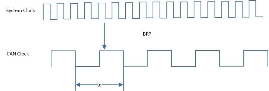
CAN Clock
During initialization, the CAN clock can be determined by BRP, which is defined in CAN_BIT_TIMING_TYPE_TypeDef::can_brp.
The effective BRP is the set value plus 1.
CAN does not have a clock line, so it uses bit synchronization to ensure the timing of communication and to correctly sample the bus levels. The CAN bit timing is as follows.
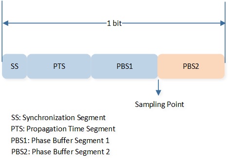
CAN Bit Timing
-
SS
The units on the bus perform timing adjustments through this segment.
The length is fixed at 1 tq.
-
PTS
A segment used to absorb physical delays on the network. The unit is tq.
-
PBS1
A segment used for compensation when adjusting timing. The unit is tq.
Defined in
CAN_BIT_TIMING_TYPE_TypeDef::can_tseg1.
-
PBS2
A segment used for compensation when adjusting timing. The unit is tq.
Defined in
CAN_BIT_TIMING_TYPE_TypeDef::can_tseg2.
-
SJW
Resynchronization jump width, the maximum value for compensation. The unit is tq.
Defined in
CAN_BIT_TIMING_TYPE_TypeDef::can_sjw.
\(TSEG1 = PTS + PBS1\).
\(TSEG2 = PBS2\).
The actual effective values of TSEG1 and TSEG2 are the set values plus 1.
Note
\(CAN Speed = 40000000 / ((BRP + 1)*(1 + TSEG1 + 1 + TSEG2 + 1))\).
The setting ranges for BRP, TSEG1, SJW, and TSEG2 in Standard CAN are as follows.
Parameter |
Min |
Max |
|---|---|---|
BRP |
0 |
31 |
TSEG1 |
1 |
15 |
TSEG2 |
1 |
7 |
SJW |
1 |
4 |
Power Manager
The CAN peripheral is located in the core domain and will be powered off in low power mode.
CAN peripheral store/restore will be automatically performed based on whether the CAN clock is active.
Users can call the API io_dlps_register() to initialize CAN peripheral store/restore and do not need to worry about CAN peripheral requiring specific handling.
For more details, please refer to Transmit and Receive - DLPS.
If using GDMA function, users need to reinitialize GDMA when exiting DLPS. For more details, please refer to Transmit and Receive - GDMA DLPS.