Transmit and Receive
This sample demonstrates the data transmission and reception capabilities of the CAN peripheral.
Connect the USB CAN analyzer to communicate with the CAN controller via the PC by sending and receiving standard data frames, extended data frames, standard remote frames, and extended remote frames.
The SoC side receives the data from the PC in the CAN interrupt and transmits the same data to the PC side, which receives the data back from the SoC.
Requirements
For hardware requirements, please refer to the Requirements.
Wiring
The EVB is connected to a TJA1051 CAN Receiver module by connecting P4_0 to CTX, P4_1 to CRX. The EVB BAT/5V is connected to the module VCC and NC. The EVB GND is connected to the module GND and S.
The other end of the TJA1051 CAN Receiver module is connected to the PC via a USB CAN analyzer, by connecting module CANH to analyzer CANH and module CANL to analyzer CANL.
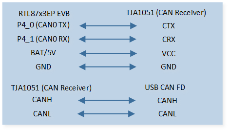
CAN TRX Demo Code Hardware Connection Diagram
CAN Transceiver Introduction
The module adopts TJA1051, which is a high-speed CAN transceiver that provides differential transmission and reception functions for the CAN controller, with a transmission rate of up to 1Mbit/s. Any other CAN transceivers could be used instead.
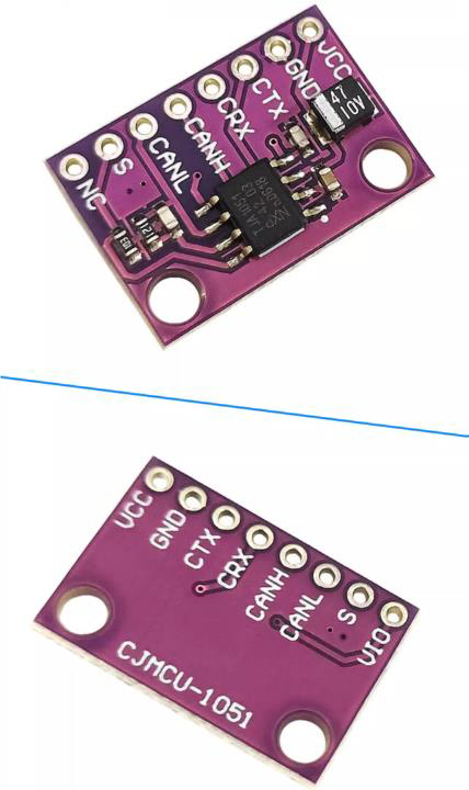
CAN transceiver module
Configurations
-
The following macros can be configured to enable the CAN RX FIFO function.
#define CAN_RX_FIFO_EN 0 -
The following macros can be configured to enable the CAN time stamp function.
#define CAN_TIME_STAMP_EN 0 -
The following macros can be configured to modify CAN pin definitions.
#define CAN_TX_PIN          P4_0
#define CAN_RX_PIN          P4_1
-
The entry function is as follows, call this function in
main()to run this sample code. For more details, please refer to the Initialization.can_trx_demo();
Building and Downloading
For building and downloading, please refer to the Building and Downloading.
Experimental Verification
-
Press the Reset button on the EVB and the message will be displayed in the Debug Analyzer.
can_trx_demo: start!
After IC reset, frames of each type are received on the CAN Tool.
Use the tool to send data frames to the IC.
-
On the Debug Analyzer, print the received frame data.
can_trx_demo: send standard data frame
can_trx_handler: MB_0 tx done
...
can_basic_rx: waiting for rx...
can_trx_handler: MB_7 rx done
can_trx_handler: frame_type 1, frame_id = 0x100, ext_frame_id = 0x00000
can_trx_handler: rx_data [0] 0x01
...
can_basic_rx: waiting for rx...
can_trx_handler: MB_0 tx done
The IC sends the received data frames back to the tool, and it can see the sent and received data frames on the tool.
Code Overview
This section introduces the code and process description for initialization and corresponding function implementation in the sample.
Source Code Directory
The directory for project file and source code are as follows.
For project directory, please refer to Source Code Directory.
Source code directory:
sdk\sample\io_demo\canbus\trx\can_trx.c.
Initialization
The initialization flow for peripherals can refer to Initialization Flow.
CAN initialization flow is shown in the following figure.
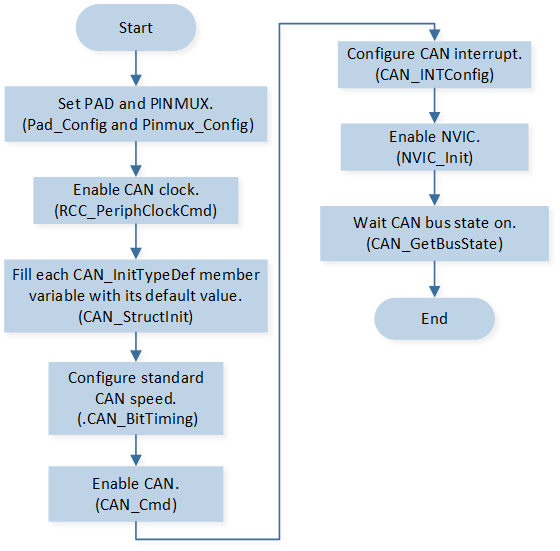
CAN Init Flow
-
Call
Pad_Config()andPinmux_Config()to configure the corresponding pin’s PAD and PINMUX.static void can_board_init(void) { /* Config pinmux and pad for CAN. */ Pinmux_Config(CAN_TX_PIN, CAN_TX); Pinmux_Config(CAN_RX_PIN, CAN_RX); Pad_Config(CAN_TX_PIN, PAD_PINMUX_MODE, PAD_IS_PWRON, PAD_PULL_NONE, PAD_OUT_DISABLE, PAD_OUT_LOW); Pad_Config(CAN_RX_PIN, PAD_PINMUX_MODE, PAD_IS_PWRON, PAD_PULL_NONE, PAD_OUT_DISABLE, PAD_OUT_LOW); }
Call
RCC_PeriphClockCmd()to enable the CAN clock.-
Initialize the CAN peripheral:
Define a
CAN_InitTypeDeftypeinit_structand callCAN_StructInit()to pre-fillinit_structwith default values.Modify the
init_structparameters as needed. The CAN initialization parameters are configured as shown in the table below.Call
CAN_Init()to initialize the parameters and the CAN peripheral.
CAN Hardware Parameters |
Setting in the |
CAN |
|---|---|---|
Auto Re-transmit Enable |
||
CAN speed parameter - BRP |
3 |
|
CAN speed parameter - SJW |
3 |
|
CAN speed parameter - TSEG1 |
13 |
|
CAN speed parameter - TESG2 |
4 |
Call
CAN_Cmd()to enable the corresponding CAN peripheral.Call
CAN_INTConfig()to configure the CAN receive completeCAN_RX_INTinterrupt, transmit completeCAN_TX_INTinterrupt, error interruptCAN_ERROR_INT, etc. Configure NVIC, and refer to Interrupt Configuration for NVIC-related configurations.-
Call
CAN_GetBusState()to loop-check the CAN bus state and wait for the CAN bus to open.while (CAN_GetBusState(CAN0) != CAN_BUS_STATE_ON) { __asm volatile ( "nop \n" ); }
Note
If the program is stuck at the point of waiting for the CAN bus to be on, please check if the CAN bus is connected correctly.
Functional Implementation
CAN TX flow is shown in the following figure.
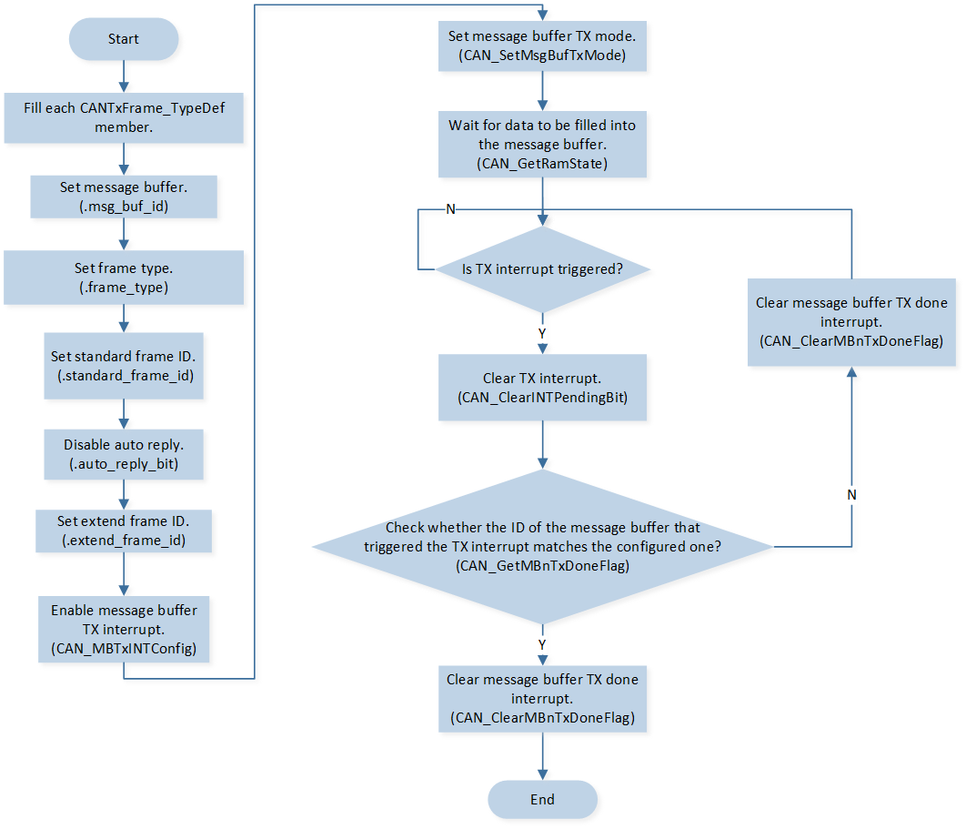
CAN TX Flow
CAN RX flow is shown in the following figure.
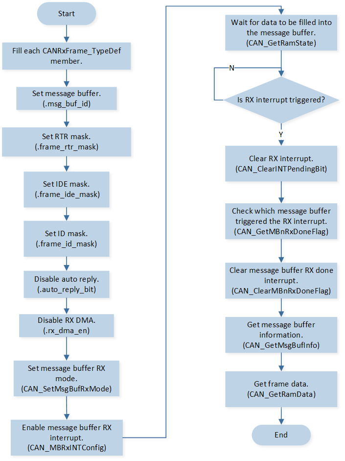
CAN RX Flow
-
Call
can_basic_tx, send a standard data frame, an extended data frame, a standard remote frame, an extended remote frame.Configure the message buffer to TX mode using the set transmit frame type.
Enable the message buffer TX interrupt. Poll the RAM status to be idle.
void can_basic_tx(uint32_t buf_id, uint8_t frame_type, \
              uint16_t frame_id, uint32_t ext_id, uint8_t *tx_data, uint8_t data_len)
{
    CANError_TypeDef tx_error;
    CANTxFrame_TypeDef tx_frame_type;
    tx_frame_type.msg_buf_id = buf_id;
    tx_frame_type.frame_type = frame_type;
    tx_frame_type.standard_frame_id = frame_id;
    tx_frame_type.auto_reply_bit = DISABLE;
    tx_frame_type.extend_frame_id = 0;

    switch (frame_type)
    {
        ...
    }

    CAN_MBTxINTConfig(CAN0, tx_frame_type.msg_buf_id, ENABLE);
    tx_error = CAN_SetMsgBufTxMode(CAN0, &tx_frame_type, tx_data, data_len);

    ...
}
Note
If sending several frames using the same message buffer id, make sure to wait for the previous frame to be already sent before sending the next frame.
After sending, call
can_basic_rxand wait for the PC to send a frame into the receive interrupt.
Use message buffer 12 to receive frame if FIFO mode is enabled.
Mask the rtr, ide, and id bit filters to receive all frames.
Disable Rx GDMA. Disable auto reply.
Configure the message buffer to RX mode using the set receive frame type.
Enable the message buffer RX interrupt. Poll the RAM status to be idle.
void can_basic_rx(void)
{
    CANError_TypeDef rx_error;
    CANRxFrame_TypeDef rx_frame_type;
#if CAN_RX_FIFO_EN
    rx_frame_type.msg_buf_id = CAN_MESSAGE_FIFO_START_ID;
#else
    rx_frame_type.msg_buf_id = 7;
#endif

    rx_frame_type.extend_frame_id = 0;
    rx_frame_type.standard_frame_id = 0;
    rx_frame_type.frame_rtr_mask = CAN_RX_FRAME_MASK_RTR;
    rx_frame_type.frame_ide_mask = CAN_RX_FRAME_MASK_IDE;
    rx_frame_type.frame_id_mask = CAN_RX_FRAME_MASK_ID;
    rx_frame_type.rx_dma_en = RESET;
    rx_frame_type.auto_reply_bit = RESET;
    rx_error = CAN_SetMsgBufRxMode(CAN0, &rx_frame_type);

    CAN_MBRxINTConfig(CAN0, rx_frame_type.msg_buf_id, ENABLE);

    ...
}
-
When transmission is complete, reception is complete, or when an error occurs, enter interrupt handler function
can_trx_handler.Read and print the received frame data sequentially from the message buffer that generated the receive completion interrupt.
Execute
can_basic_txto send back the received frame type and frame data.Execute
can_basic_rxand wait for the next interrupt.
...
CAN_ClearMBnRxDoneFlag(CAN0, index);
CANMsgBufInfo_TypeDef mb_info;
CAN_GetMsgBufInfo(CAN0, index, &mb_info);
...
CAN_GetRamData(CAN0, mb_info.data_length, rx_data);
CANDataFrameSel_TypeDef frame_type = CAN_CheckFrameType(mb_info.rtr_bit, mb_info.ide_bit,
                                                                        mb_info.edl_bit);
...
/* Send back frame here. */
can_basic_tx(0, frame_type, mb_info.standard_frame_id, \
              mb_info.extend_frame_id, rx_data, mb_info.data_length);

/* Start rx next time. */
can_basic_rx();
...