VBAT and NTC Detection
This sample code guide is designed to help users easily and comprehensively understand ADC sample. This sample demonstrates how ADC samples NTC and VBAT voltage. This sample uses one shot mode of the ADC peripheral to measure voltage on VBAT and NTC by ADC manager.
Requirements
For hardware requirements, please refer to the Requirements.
Wiring
Connect P0_0 and P0_1 of EVB to an external DC voltage source and input voltage must range from 0 to 0.9V.
Connect Lithium-ion battery to EVB.
Configurations
-
The following macros can be configured to modify the sampling interval.
#define ADC_READ_VBAT_NTC_VOLTAGE_TIMEOUT_MS 500
-
The entry function is as follows, call this function in
main()to run this sample code. For more details, please refer to the Initialization.adc_charger_demo();
Building and Downloading
For building and downloading, please refer to the Building and Downloading.
Experimental Verification
Press the Reset button on the EVB board, ADC samples every 500ms. Once ADC sampling is finished, the converted voltage values will be printed in Debug Analyzer.
app_adc_vbat_ntc_voltage_read_callback: temperature_battery_1 xxx, temperature_battery_2 xxx, voltage_battery xxx
Code Overview
This section introduces the code and process description for initialization and corresponding function implementation in the sample.
Source Code Directory
For project directory, please refer to Source Code Directory.
Source code directory:
sdk\src\sample\io_demo\adc\adc_charger_demo\adc_charger_demo.c.
Initialization
The initialization flow of ADC sampling in one shot mode by ADC manager is shown in the following figure.
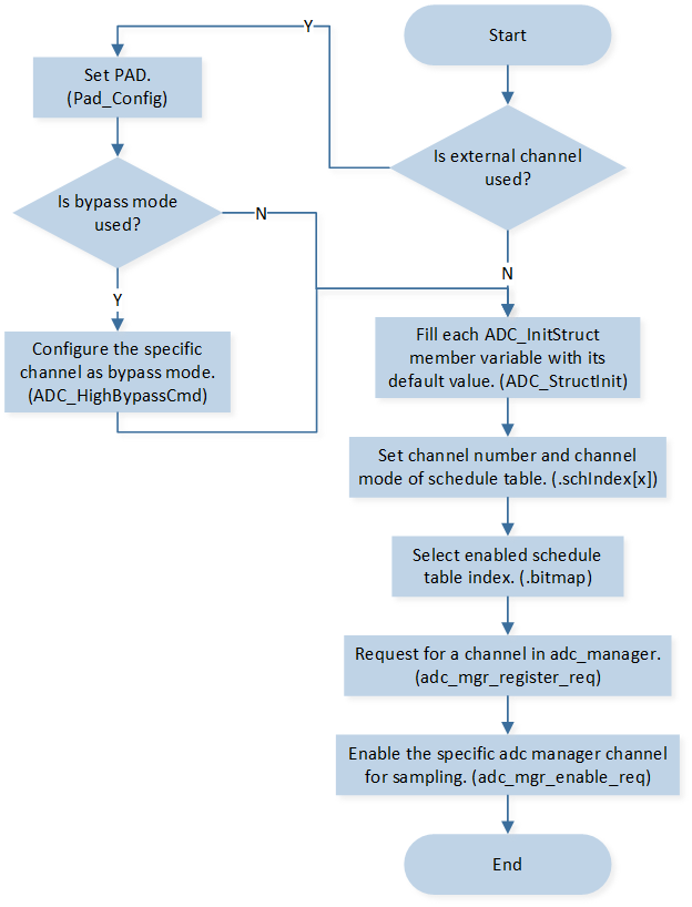
ADC One Shot Sampling by ADC Manager Mode
-
Call
Pad_Config()andPinmux_Config()to initialize the pin.static void board_adc_init(void) { Pad_Config(ADC_0, PAD_SW_MODE, PAD_IS_PWRON, PAD_PULL_NONE, PAD_OUT_DISABLE, PAD_OUT_LOW); Pad_Config(ADC_1, PAD_SW_MODE, PAD_IS_PWRON, PAD_PULL_NONE, PAD_OUT_DISABLE, PAD_OUT_LOW); Pinmux_Config(ADC_0, IDLE_MODE); Pinmux_Config(ADC_1, IDLE_MODE); }
Call
ADC_HighBypassCmd()to configure the specific channel as bypass mode.-
Initialize the ADC peripheral:
Define the
ADC_InitTypeDeftypeADC_InitStruct, and callADC_StructInit()to pre-fillADC_InitStructwith default values.Modify the
ADC_InitStructparameters as needed. The ADC initialization parameter configuration is shown in the table below.Call
adc_mgr_register_req()to request for a channel in ADC manager and initialize the ADC peripheral.
ADC Initialization Parameters ADC Hardware Parameters
Setting in the
ADC_InitStructVariablesADC
Sample Time
Bit Map
0x07
Schedule Index
Index 0 is set to
EXT_SINGLE_ENDED(0).Index 1 is set to
EXT_SINGLE_ENDED(1).Index 2 is set to
INTERNAL_VBAT_MODE. Call
adc_mgr_enable_req()to enable the specific ADC manager channel for sampling.
Functional Implementation
Callback Handle
When ADC sampling is completed, ADC manager callback function will be executed. ADC manager callback handle flow is shown in the following figure.
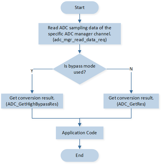
ADC Manager Callback Handle Flow
Call
adc_mgr_read_data_req()to read ADC sampling raw data of the specific ADC manager channel.Call
ADC_GetRes()andADC_GetHighBypassRes()to get conversion result.