ADC Key Detection
This sample code guide is designed to help users easily and comprehensively understand ADC sample. This sample demonstrates how to detect key presses using ADC and LPC.
Requirements
For hardware requirements, please refer to the Requirements.
Wiring
Connect P0_3 to an external key module.
The hardware connection of ADC sample code is shown in the figure below.
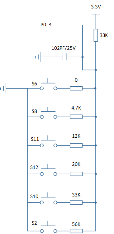
ADC Sample Code Hardware Connection Diagram
Configurations
-
The entry function is as follows, call this function in
main()to run this sample code. For more details, please refer to the Initialization.adc_key_demo();
Building and Downloading
For building and downloading, please refer to the Building and Downloading.
Experimental Verification
-
Press the Reset button on the EVB board, when a key is pressed, the key information will be printed in Debug Analyzer.
io_demo_app_task: key mask xx, key_press 1
-
When the key is released, the key information will be printed in Debug Analyzer.
io_demo_app_task: key mask xx, key_press 0
Code Overview
This section introduces the code and process description for initialization and corresponding function implementation in the sample.
Source Code Directory
For project directory, please refer to Source Code Directory.
Source code directory:
sdk\src\sample\io_demo\adc\adc_key\adc_key_demo.c.
Initialization
-
Initialize the ADC peripheral:
Define the
ADC_InitTypeDeftypeADC_InitStruct, and callADC_StructInit()to pre-fillADC_InitStructwith default values.Modify the
ADC_InitStructparameters as needed. The ADC initialization parameter configuration is shown in the table below.Call
adc_mgr_register_req()to request for a channel in ADC manager and initialize the ADC peripheral.
ADC Initialization Parameters ADC Hardware Parameters
Setting in the
ADC_InitStructVariablesADC
Sample Time
Bit Map
0x0001
Schedule Index
Index 0 is set to
EXT_SINGLE_ENDED(3). -
Call
Pad_Config()andPinmux_Config()to initialize the pin to LPC function.static void board_lpc_init(void) { Pad_Config(ADC_SAMPLE_PIN, PAD_PINMUX_MODE, PAD_IS_PWRON, PAD_PULL_NONE, PAD_OUT_DISABLE, PAD_OUT_HIGH); Pinmux_Config(ADC_SAMPLE_PIN, IDLE_MODE); }
-
Initialize the LPC peripheral:
Define the
LPC_InitTypeDeftypeLPC_InitStruct, and callLPC_StructInit()to pre-fillLPC_InitStructwith default values.Modify the
LPC_InitStructparameters as needed. The LPC initialization parameter configuration is shown in the table below.Call
LPC_Init()to initialize the LPC peripheral.
LPC Initialization Parameters LPC Hardware Parameters
Setting in the
LPC_InitStructLPC
Channel
ADC_SAMPLE_PINEdge
Threshold Voltage
Call
LPC_CounterReset()to reset the LPC counter.Call
LPC_WriteComparator()to set LPC comparator value.Call
LPC_INTConfig()to enable the LPC comparator interruptLPC_INT_COUNT_COMP.For RTL87x3D, call
LPC_INTConfig()to enable interrupt signal to CPU NVIC, for RTL87x3E and RTL87x3EP, callRTC_CpuNVICEnable()to enable interrupt signal to CPU NVIC.For RTL87x3D, call
NVIC_Init()to enable NVIC of LPC, for RTL87x3E and RTL87x3EP, callNVIC_Init()to enable NVIC of RTC.Call
LPC_Cmd()to enable the LPC.Call
LPC_CounterCmd()to enable the LPC counter.
DLPS Mode Initialization
Call
io_dlps_register()to initialize IO store/restore and do not need to worry about which IO peripheral requires specific handling.-
Call
io_dlps_register_enter_cb()to register callbacks to DLPS enter stage. Functionio_dlps_enter_callbackwill be executed while entering from DLPS:Call
RTC_SystemWakeupConfig()to enable the LPC system wakeup function.
Call
bt_power_mode_set()to set Bluetooth MAC deep sleep mode.Call
power_mode_set()to switch the system to DLPS mode.
Functional Implementation
LPC Interrupt Handle
When the LPC detects that the input voltage exceeds the set voltage threshold (LPC_3000_mV), it triggers an interrupt:
Call
LPC_GetINTStatus()to checkLPC_INT_COUNT_COMPinterrupt status flag.Call
LPC_CounterReset()to reset the LPC counter.Call
LPC_ClearINTPendingBit()to clear the LPC comparator interruptLPC_INT_COUNT_COMP.-
Send a message to the task, and after the task receives the message:
Call
LPC_Cmd()to disable the LPC.Call
LPC_CounterCmd()to disable the LPC counter.Call
Pad_Config()andPinmux_Config()to initialize the pin to ADC function.
static void board_adc_init(void)
{
   Pad_Config(ADC_SAMPLE_PIN, PAD_SW_MODE, PAD_IS_PWRON, PAD_PULL_NONE, PAD_OUT_DISABLE, PAD_OUT_LOW);
   Pinmux_Config(ADC_SAMPLE_PIN, IDLE_MODE);
}
Call
adc_mgr_enable_req()to enable the specific ADC manager channel for sampling.
ADC Manager Callback Handle
When ADC sampling is completed, ADC manager callback function adc_key_read_voltage_callback will be executed.
Call
adc_mgr_read_data_req()to read ADC sampling raw data of the specific ADC manager channel.Call
ADC_GetRes()to get ADC conversion result, and get the key indexkey_indexbased on the conversion result.-
If the key index
key_indexis not equal to 0xff, it means a key is pressed, and the edge of LPC is adjusted toLPC_Vin_Over_Vthto detect key release.-
If
adc_key_data.key_press[key_index]is equal toKEY_RELEASE, it means that the last state of this key was released.Set
key_status_update_fgto 1.Set
adc_key_data.key_press[key_index]to update the key state.Set
adc_key_data.key_indexto update the key index.
-
Call
Pad_Config()andPinmux_Config()to initialize the pin to LPC function.static void board_lpc_init(void) { Pad_Config(ADC_SAMPLE_PIN, PAD_PINMUX_MODE, PAD_IS_PWRON, PAD_PULL_NONE, PAD_OUT_DISABLE, PAD_OUT_HIGH); Pinmux_Config(ADC_SAMPLE_PIN, IDLE_MODE); }
Call
LPC_SetTriggerEdge()to set LPC trigger edge toLPC_Vin_Over_Vth.Call
LPC_Cmd()to enable the LPC.Call
LPC_CounterCmd()to enable the LPC counter.
-
-
If the key index
key_indexis equal to 0xff, it means a key is released, and the edge of LPC is adjusted toLPC_Vin_Below_Vthto detect key press.-
If
adc_key_data.key_indexis not equal to 0xff andadc_key_data.key_press[adc_key_data.key_index]is equal toKEY_PRESS, it means that the last state of this key was pressed.Set
key_status_update_fgto 1.Set
adc_key_data.key_press[adc_key_data.key_index]to update the key state.Set
adc_key_data.key_indexto update the key index.
-
Call
Pad_Config()andPinmux_Config()to initialize the pin to LPC function.static void board_lpc_init(void) { Pad_Config(ADC_SAMPLE_PIN, PAD_PINMUX_MODE, PAD_IS_PWRON, PAD_PULL_NONE, PAD_OUT_DISABLE, PAD_OUT_HIGH); Pinmux_Config(ADC_SAMPLE_PIN, IDLE_MODE); }
Call
LPC_SetTriggerEdge()to set LPC trigger edge toLPC_Vin_Below_Vth.Call
LPC_Cmd()to enable the LPC.Call
LPC_CounterCmd()to enable the LPC counter.
-
If
key_status_update_fgis set to 1, send a message to the task, and after the task receives the message, print key information.