SLEEP LED Breathe Mode
This sample code guide is designed to help users easily and comprehensively understand SLEEP LED sample. In this sample, SLEEP LED is configured in breathe mode.
Requirements
For hardware requirements, please refer to the Requirements.
Wiring
On EVB, connect P0_1 to LED1 and connect P2_1 to LED2 and connect P2_2 to LED3.
The hardware connection of SLEEP LED sample code is shown in the figure below.
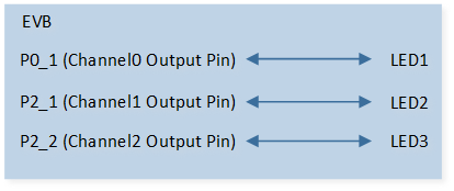
SLEEP LED Sample Code Hardware Connection Diagram
Configurations
-
The following macros can be configured to modify pin definitions.
#define LED_OUT_0 ADC_1#define LED_OUT_1 P2_1#define LED_OUT_2 P2_2
-
The entry function is as follows, call this function in
main()to run this sample code. For more details, please refer to the Initialization.sleep_led_breathe_demo();
Building and Downloading
For building and downloading, please refer to the Building and Downloading.
Experimental Verification
Press the Reset button on the EVB board, LEDs turn from dark to bright and then from bright to dark in breathe mode.
Code Overview
This section introduces the code and process description for initialization and corresponding function implementation in the sample.
Source Code Directory
For project directory, please refer to Source Code Directory.
Source code directory:
sdk\src\sample\io_demo\led\sleep_led_demo.c.
Initialization
The initialization flow for peripherals can refer to Initialization Flow.
The initialization flow of SLEEP LED breathe mode is shown in the following figure.
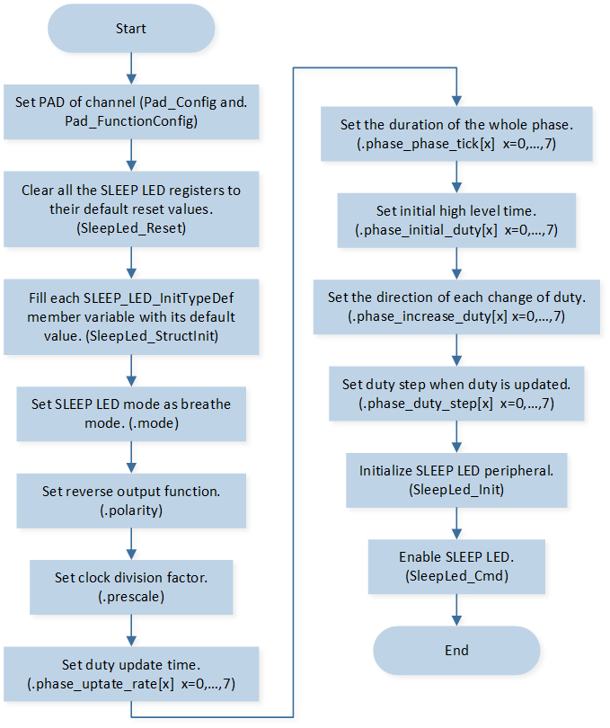
SLEEP LED Breathe Mode Initialization Flow Chart
-
Call
Pad_Config()andPad_FunctionConfig()to initialize the pin.static void board_led_init(void) { Pad_Config(LED_OUT_0, PAD_SW_MODE, PAD_IS_PWRON, PAD_PULL_NONE, PAD_OUT_ENABLE, PAD_OUT_HIGH); Pad_Config(LED_OUT_1, PAD_SW_MODE, PAD_IS_PWRON, PAD_PULL_NONE, PAD_OUT_ENABLE, PAD_OUT_HIGH); Pad_Config(LED_OUT_2, PAD_SW_MODE, PAD_IS_PWRON, PAD_PULL_NONE, PAD_OUT_ENABLE, PAD_OUT_HIGH); Pad_FunctionConfig(LED_OUT_0, LED0); Pad_FunctionConfig(LED_OUT_1, LED1); Pad_FunctionConfig(LED_OUT_2, LED2); }
Call
SleepLed_Reset()to clear all SLEEP LED registers to their default reset values.-
Initialize the SLEEP LED peripheral:
Define the
SLEEP_LED_InitTypeDeftypeLed_Initsturcture, and callSleepLed_StructInit()to pre-fillLed_Initsturcturewith default values.Modify the
Led_Initsturctureparameters as needed. The SLEEP LED initialization parameter configuration is shown in the table below.Call
SleepLed_Init()to initialize the SLEEP LED peripheral.
SLEEP LED Initialization Parameters SLEEP LED Hardware Parameters
Setting in the
Led_InitsturctureVariablesSLEEP LED
Clock Division Factor
320
Mode
Polarity
Duty Update Time
Phase0: 0 (10ms)
Phase1: 0 (10ms)
Phase2: 0 (10ms)
Phase3: 0 (10ms)
Phase4: 0 (10ms)
Phase5: 0 (10ms)
Phase6: 0 (10ms)
Phase7: 0 (10ms)
The Duration of The Whole Phase
Phase0: 50 (500ms)
Phase1: 50 (500ms)
Phase2: 50 (500ms)
Phase3: 50 (500ms)
Phase4: 50 (500ms)
Phase5: 50 (500ms)
Phase6: 50 (500ms)
Phase7: 50 (500ms)
Initial High Level Time
Phase0: 0 (0)
Phase1: 100 (3.125ms)
Phase2: 200 (6.25ms)
Phase3: 300 (9.375ms)
Phase4: 300 (9.375ms)
Phase5: 200 (6.25ms)
Phase6: 100 (3.125ms)
Phase7: 0 (0)
Duty Step Time
Phase0: 1 (0.03125ms)
Phase1: 2 (0.0625ms)
Phase2: 3 (0.09375ms)
Phase3: 4 (0.125ms)
Phase4: 1 (0.03125ms)
Phase5: 2 (0.0625ms)
Phase6: 3 (0.09375ms)
Phase7: 0 (0)
The Direction of Each Change of Duty
Phase0: 1 (increase)
Phase1: 1 (increase)
Phase2: 1 (increase)
Phase3: 1 (increase)
Phase4: 0 (decrease)
Phase5: 0 (decrease)
Phase6: 0 (decrease)
Phase7: 0 (decrease)
Call
SleepLed_Cmd()to enable SLEEP LED.