PWM Normal and Complementary Output
This sample code guide is designed to help users easily and comprehensively understand PWM sample. This sample demonstrates PWM output, PWM complementary output, and deadzone.
Requirements
For hardware requirements, please refer to the Requirements.
Wiring
Connect P0_0 of EVB to channel 0 of the logic analyzer, connect P0_2 of EVB to channel 1 of the logic analyzer, and connect P0_3 of EVB to channel 2 of the logic analyzer.
Configurations
-
The following macros can be configured to modify pin definitions.
#define PWM_OUT_PIN ADC_0#define PWM_OUT_PIN_P ADC_2#define PWM_OUT_PIN_N ADC_3
-
The following macros can be configured to modify the high level time and low level time of PWM.
#define PWM_HIGH_LEVEL_CNT 2000#define PWM_LOW_LEVEL_CNT 2000
-
The following macros can be configured to modify deadzone time.
#define PWM_DEADZONE_SIZE_CNT 0x10
-
The entry function is as follows, call this function in
main()to run this sample code. For more details, please refer to the Initialization.pwm_demo();
Building and Downloading
For building and downloading, please refer to the Building and Downloading.
Experimental Verification
Press the Reset button on the EVB, the waveforms displayed by channels 0/1/2 of the logic analyzer are shown the figure below.
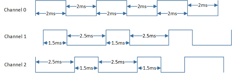
PWM Sample Code Expected Result Diagram
Code Overview
This section introduces the code and process description for initialization and corresponding function implementation in the sample.
Source Code Directory
For project directory, please refer to Source Code Directory.
Source code directory:
sdk\src\sample\io_demo\tim\pwm\pwm_demo.c.
Initialization
Normal Output
Call
pwm_create()to create a PWM with a high level time of 2ms and a low level time of 2ms.Call
pwm_pin_config()to configure PWM output pin.Call
pwm_start()to start the PWM.
Complementary Output and Deadzone
Call
pwm_create()to create a PWM with a high level time of 2ms, a low level time of 2ms and deadzone enabled.Define the
T_PWM_CONFIGtypedemo_pwm_deadzone_para, and modify thedemo_pwm_deadzone_paraparameters. The PWM parameters configuration is shown in the table below.
PWM Hardware Parameters |
Setting in the |
PWM |
|---|---|---|
PWM High Count |
2000 |
|
PWM Low Count |
2000 |
|
PWM Deadzone Enable |
||
PWM Clock Source |
||
Deadzone Time |
0x10 |
|
PWM P Stop State |
||
PWM N Stop State |
Call
pwm_config()to configure PWM according to the parameters.Call
pwm_pin_config()to configure PWM output pin.Call
pwm_start()to start the PWM.