I2S Master Send
This sample code demonstrates I2S data transmission function by using TX polling. In this sample, I2S is configured as the master. The chip sends data to I2S slave continuously.
Requirements
For hardware requirements, please refer to the Requirements.
Wiring
Connect P0_0 to the LRCK of the I2S slave, connect P0_1 to the BCLK of the I2S slave, and connect P0_2 to the SDI of the I2S slave.
The hardware connection of I2S sample code is shown in the figure below.
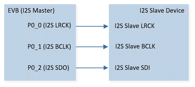
I2S Sample Code Hardware Connection Diagram
Configurations
-
The following macros can be configured to modify pin definitions.
#define I2S_LRCK_PIN P0_0#define I2S_BCLK_PIN P0_1#define I2S_SDO_PIN P0_2
-
The entry function is as follows, call this function in
main()to run this sample code. For more details, please refer to the Initialization.i2s_master_send_demo();
Building and Downloading
For building and downloading, please refer to the Building and Downloading.
Experimental Verification
Code Overview
Source Code Directory
For project directory, please refer to Source Code Directory.
Source code directory:
sdk\src\sample\io_demo\i2s\master_send\i2s_master_send_demo.c.
Initialization
The initialization flow for peripherals can refer to Initialization Flow.
I2S initialization flow is shown in the following figure.
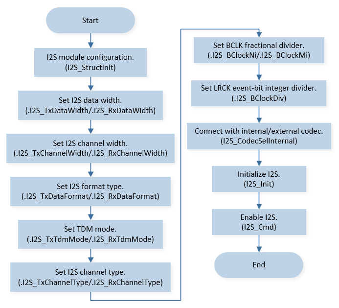
I2S Master Init Flow Chart
Note
As mentioned in PINMUX and PAD function descriptions, I2S PAD should be configured as software mode and pulled down when I2S is disabled to prevent PAD from floating during low power mode.
-
Call
Pad_Config()andPinmux_Config()to initialize the pin.static void board_i2s_init(void) { /* set PAD_SW_MODE & PAD_PULL_DOWN when I2S disable to prevent PAD floating */ Pad_Config(I2S_BCLK_PIN, PAD_PINMUX_MODE, PAD_IS_PWRON, PAD_PULL_NONE, PAD_OUT_ENABLE, PAD_OUT_LOW); Pad_Config(I2S_LRCK_PIN, PAD_PINMUX_MODE, PAD_IS_PWRON, PAD_PULL_NONE, PAD_OUT_ENABLE, PAD_OUT_LOW); Pad_Config(I2S_SDO_PIN, PAD_PINMUX_MODE, PAD_IS_PWRON, PAD_PULL_NONE, PAD_OUT_ENABLE, PAD_OUT_LOW); Pinmux_Config(I2S_BCLK_PIN, I2S_BCLK_PINMUX); Pinmux_Config(I2S_LRCK_PIN, I2S_LRCK_PINMUX); Pinmux_Config(I2S_SDO_PIN, I2S_SDO_PINMUX); }
-
Initialize the I2S peripheral:
Define the
I2S_InitTypeDeftypeI2S_InitStruct, and callI2S_StructInit()to pre-fillI2S_InitStructwith default values.Modify the
I2S_InitStructparameters as needed. The I2S initialization parameter configuration is shown in the table below.Call
I2S_Init()to initialize the I2S peripheral.
I2S Initialization Parameters I2S Hardware Parameters
Setting in the
I2S_InitStructI2S
Device Role
Bit Clock Divider (Mi)
0x271
Bit Clock Divider (Ni)
0x30
LR Clock Divider
0x3F
Data Width
Channel Width
Channel Type
Data Format
Functional Implementation
Master Send Data
The I2S master call I2S_SendData(), and send data to I2S slave repeatedly.
static void i2s_send_data(void)
{
    uint32_t pattern = 0x12345678;

    while (1)
    {
        if (I2S_GetTxFIFODepth(I2S_NUM))
        {
            /* in 16-bits format, low half word send first */
            I2S_SendData(I2S_NUM, pattern);

            /* increase high & low half word by 1 respectively */
            pattern += (BIT16 | BIT0);
        }
    }
}