I2C GDMA Mode
This sample code guide is written to help users easily and completely understand I2C sample. This sample demonstrates communication between an I2C master device and a slave device using GDMA. Meanwhile, the master and the slave are interconnected to achieve transmission that master receive data and slave transmit data.
The master device acts as the receiver, using GDMA for receive data; the slave device acts as the sender, using GDMA for transmit data.
In this sample, I2C1 is configured as the master device; I2C0 is configured as the slave device.
Requirements
For hardware requirements, please refer to the Requirements.
Wiring
Connect P0_1 (master SCL) to P1_1 (slave SCL), P0_0 (master SDA) to P1_0 (slave SDA) on the EVB, need to connect 2.2k pull-up resistor.
The hardware connection of I2C sample code is shown in the figure below.
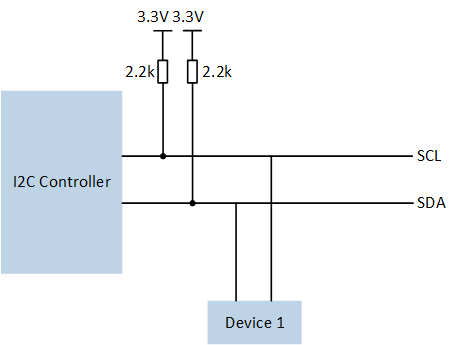
I2C Sample Code Hardware Connection Diagram
Configurations
-
The following macros can be configured to modify pin definitions.
#define I2C0_SDA P1_0#define I2C0_SCL P1_1#define I2C1_SDA P0_0#define I2C1_SCL P0_1
-
The entry function is as follows, call this function in
main()to run this sample code. For more details, please refer to the Initialization.i2c_dma_demo();
Building and Downloading
For building and downloading, please refer to the Building and Downloading.
Experimental Verification
Press the Reset button on the EVB, master send read command to slave.
-
When the slave device receives a read request from the master device, the
I2C_INT_RD_REQinterrupt is triggered which GDMA is enabled to transfer data in the interrupt handler. The slave device sends data to the master via GDMA. when completing the transmission, it enters the GDMA interrupt and prints log.i2c_tx_dma_handler -
The Master receives the data sent by the slave via GDMA, and when completing the transmission, it enters the GDMA interrupt and prints log.
i2c_rx_dma_handler
Code Overview
This section introduces the code and process description for initialization and corresponding function implementation in the sample.
Source Code Directory
For project directory, please refer to Source Code Directory.
Source code directory:
sdk\src\sample\io_demo\gdma\i2c_dma\MasterRx+SlaveTx\i2c_dma_demo.c.
I2C Master (I2C1) Initialization
I2C master mode initialization flow is shown in the following figure.
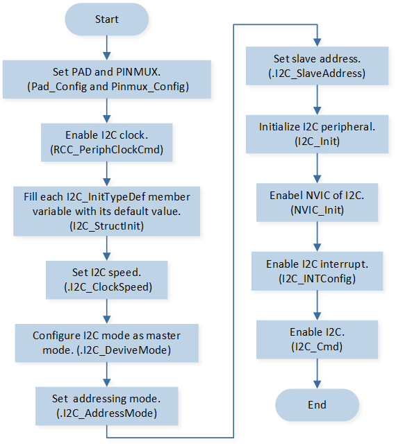
I2C Master Mode Initialization Flow Chart
-
Call
Pad_Config()andPinmux_Config()to initialize the pin.Pad_Config(I2C1_SDA, PAD_PINMUX_MODE, PAD_IS_PWRON, PAD_PULL_NONE, PAD_OUT_ENABLE, PAD_OUT_HIGH); Pad_Config(I2C1_SCL, PAD_PINMUX_MODE, PAD_IS_PWRON, PAD_PULL_NONE, PAD_OUT_ENABLE, PAD_OUT_HIGH); Pinmux_Config(I2C1_SDA, I2C1_DAT); Pinmux_Config(I2C1_SCL, I2C1_CLK);
Call
RCC_PeriphClockCmd()to enable the I2C clock and function.-
Initialize the I2C peripheral:
Define the
I2C_InitTypeDeftypeI2C_InitStructure, and callI2C_StructInit()to pre-fillI2C_InitStructurewith default values.Modify the
I2C_InitStructureparameters as needed. The I2C initialization parameter configuration is shown in the table below.Call
I2C_Init()to initialize the I2C peripheral.
I2C Initialization Parameters I2C Hardware Parameters
Setting in the
I2C_InitStructureI2C
Clock
400000
Device Role (I2C Master or I2C Slave)
Address Mode (7bits/10bits Mode)
Slave Address
0x50
Auto ACK Enable
ENABLERX GDMA Enable
RX Waterlevel
3
Call
NVIC_Init()to enable NVIC of I2C.Call
I2C_INTConfig()to enable I2C RX FIFO underflow interruptI2C_INT_RX_UNDERand stop signal detection interruptI2C_INT_STOP_DET.Call
I2C_Cmd()to enable I2C.
I2C Slave (I2C0) Initialization
I2C slave mode initialization flow is shown in the following figure.
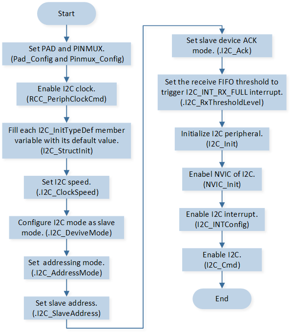
I2C Slave Mode Initialization Flow Chart
-
Call
Pad_Config()andPinmux_Config()to initialize the pin.Pad_Config(I2C0_SDA, PAD_PINMUX_MODE, PAD_IS_PWRON, PAD_PULL_NONE, PAD_OUT_ENABLE, PAD_OUT_HIGH); Pad_Config(I2C0_SCL, PAD_PINMUX_MODE, PAD_IS_PWRON, PAD_PULL_NONE, PAD_OUT_ENABLE, PAD_OUT_HIGH); Pinmux_Config(I2C0_SDA, I2C0_DAT); Pinmux_Config(I2C0_SCL, I2C0_CLK);
Call
RCC_PeriphClockCmd()to enable the I2C clock and function.-
Initialize the I2C peripheral:
Define the
I2C_InitTypeDeftypeI2C_InitStructure, and callI2C_StructInit()to pre-fillI2C_InitStructurewith default values.Modify the
I2C_InitStructureparameters as needed. The I2C initialization parameter configuration is shown in the table below.Call
I2C_Init()to initialize the I2C peripheral.
I2C Initialization Parameters I2C Hardware Parameters
Setting in the
I2C_InitStructureI2C
Clock
400000
Device Role (I2C Master or I2C Slave)
Address Mode (7bits/10bits Mode)
Slave Address
0x50
Auto ACK Enable
TX GDMA Enable
TX Waterlevel
16
Call
NVIC_Init()to enable NVIC of I2C.Call
I2C_INTConfig()to enable read request interruptI2C_INT_RD_REQand RX full interruptI2C_INT_RX_FULL.Call
I2C_Cmd()to enable I2C.
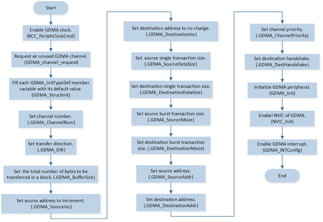
GDMA Initialization (I2C Master)
GDMA used by I2C master initialization flow is shown in the following figure.
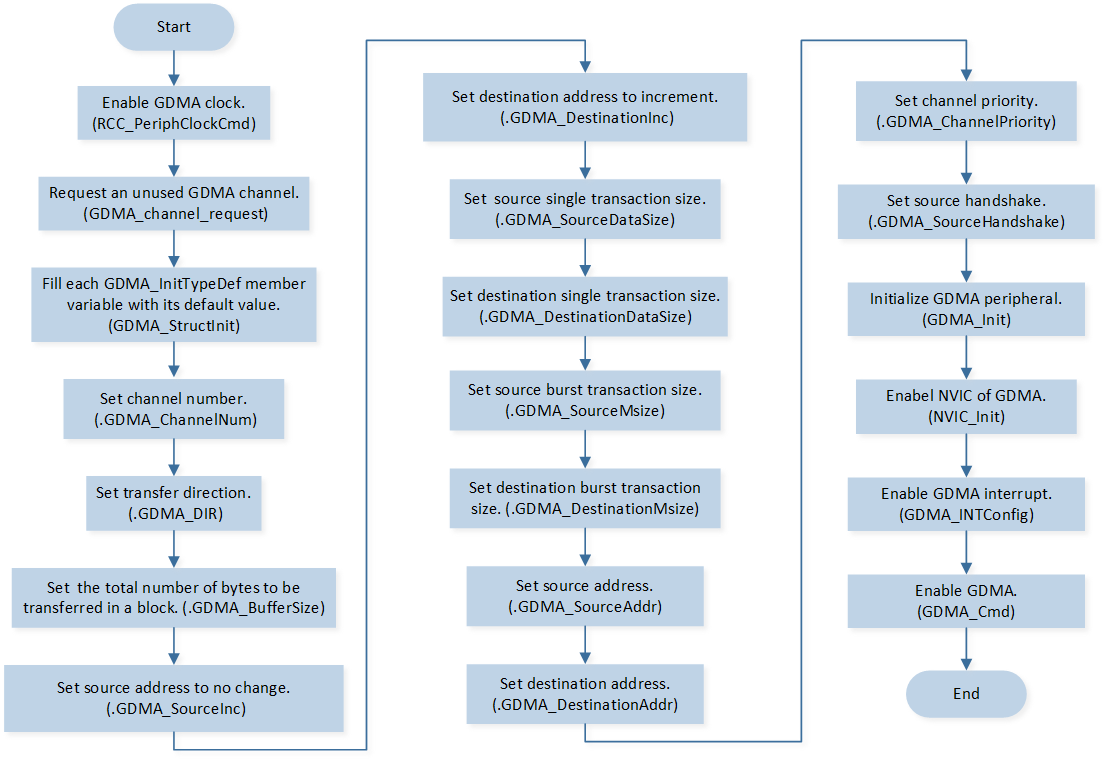
GDMA Initialization Flow Chart
Call
RCC_PeriphClockCmd()to enable the GDMA clock and function.Call
GDMA_channel_requestto request an unused GDMA channel.-
Initialize the GDMA peripheral:
Define the
GDMA_InitTypeDeftypeGDMA_InitStruct, and callGDMA_StructInit()to pre-fillGDMA_InitStructwith default values.Modify the
GDMA_InitStructparameters as needed. The GDMA initialization parameter configuration is shown in the table below.Call
GDMA_Init()to initialize the GDMA peripheral.
GDMA Initialization Parameters GDMA Hardware Parameters
Setting in the
GDMA_InitStructVariablesGDMA
Channel Num
I2C_RX_DMA_CHANNEL_NUMTransfer Direction
Buffer Size
TEST_SIZESource Address Increment or Fix
Destination Address Increment or Fix
Source Data Size
Destination Data Size
Source Burst Transaction Length
Destination Burst Transaction Length
Source Address
(uint32_t) & (I2C1->IC_DATA_CMD)Destination Address
(uint32_t)(readbuf)Source Handshake
Call
NVIC_Init()to enable NVIC of GDMA.Call
GDMA_INTConfig()to enable GDMA transfer complete interruptGDMA_INT_Transfer.Call
GDMA_Cmd()to enable GDMA.
GDMA Initialization (I2C Slave)
GDMA used by I2C slave initialization flow is shown in the following figure.
GDMA Initialization Flow Chart
Call
RCC_PeriphClockCmd()to enable the GDMA clock and function.Call
GDMA_channel_requestto request an unused GDMA channel.-
Initialize the GDMA peripheral:
Define the
GDMA_InitTypeDeftypeGDMA_InitStruct, and callGDMA_StructInit()to pre-fillGDMA_InitStructwith default values.Modify the
GDMA_InitStructparameters as needed. The GDMA initialization parameter configuration is shown in the table below.Call
GDMA_Init()to initialize the GDMA peripheral.
GDMA Initialization Parameters GDMA Hardware Parameters
Setting in the
GDMA_InitStructVariablesGDMA
Channel Num
I2C_TX_DMA_CHANNEL_NUMTransfer Direction
Buffer Size
TEST_SIZESource Address Increment or Fix
Destination Address Increment or Fix
Source Data Size
Destination Data Size
Source Burst Transaction Length
Destination Burst Transaction Length
Source Address
(uint32_t)sendbufDestination Address
(uint32_t)(&(I2C0->IC_DATA_CMD))Destination Handshake
Call
NVIC_Init()to enable NVIC of GDMA.Call
GDMA_INTConfig()to enable GDMA transfer complete interruptGDMA_INT_Transfer.
Functional Implementation
I2C Master Send Read Command
Call
I2C_SendCmd()to send read command to slave.Call
I2C_GetFlagState()to checkI2C_FLAG_TFNFflag status and wait for transmit FIFO is full.Repeat the above process and send all read command.
I2C Master Interrupt Handle
-
When the master detects a stop signal, stop signal detection interrupt will be triggered and enters the interrupt handler:
Call
I2C_GetINTStatus()to checkI2C_INT_STOP_DETinterrupt status.Call
I2C_ClearINTPendingBit()to clearI2C_INT_STOP_DETinterrupt.
-
When the processor attempts to read an empty FIFO, I2C RX FIFO underflow interrupt will be triggered and enters the interrupt handler:
Call
I2C_GetINTStatus()to checkI2C_INT_RX_UNDERinterrupt status.Call
I2C_ClearINTPendingBit()to clearI2C_INT_RX_UNDERinterrupt.
I2C Slave Interrupt Handle
-
When the receive buffer reaches or goes above the receive FIFO threshold level (
I2C_InitTypeDef::I2C_RxThresholdLevel+ 1), RX full interrupt will be triggered and enters the interrupt handler:Call
I2C_GetINTStatus()to checkI2C_INT_RX_FULLinterrupt status.Call
I2C_INTConfig()to disable RX full interruptI2C_INT_RX_FULL.Call
I2C_ClearINTPendingBit()to clearI2C_INT_RX_FULLinterrupt.
-
When I2C master is attempting to read data from I2C slave, read request interrupt will be triggered and enters the interrupt handler:
Call
I2C_GetINTStatus()to checkI2C_INT_RD_REQinterrupt status.Call
GDMA_Cmd()to enable GDMA to send data to master.Call
I2C_ClearINTPendingBit()to clearI2C_INT_RD_REQinterrupt.Call
I2C_INTConfig()to disable read request interruptI2C_INT_RD_REQ.
GDMA (I2C Master) Interrupt Handle
When GDMA transfer is completed, transfer complete interrupt is triggered:
Call
GDMA_INTConfig()to disable GDMA transfer complete interruptGDMA_INT_Transfer.Call
GDMA_ClearINTPendingBit()to clearGDMA_INT_Transferinterrupt.Call
GDMA_channel_release()to release the GDMA channel used by I2C master.
GDMA (I2C Slave) Interrupt Handle
When GDMA transfer is completed, transfer complete interrupt is triggered:
Call
GDMA_INTConfig()to disable GDMA transfer complete interruptGDMA_INT_Transfer.Call
GDMA_ClearINTPendingBit()to clearGDMA_INT_Transferinterrupt.Call
GDMA_channel_release()to release the GDMA channel used by I2C slave.