I2C Master Mode
This sample code guide is written to help users easily and completely understand I2C sample. This sample demonstrates I2C write and then read data function in polling mode and stop signal detection in master mode. In this sample, I2C is configured as the master. The chip writes some data to I2C slave and then chip reads data from I2C slave.
Requirements
For hardware requirements, please refer to the Requirements.
Wiring
Connect P0_0 to the SCL of the I2C slave, connect P0_1 to the SDA of the I2C slave, need to connect 2.2k pull-up resistor.
The hardware connection of I2C sample code is shown in the figure below.
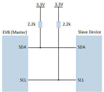
I2C Sample Code Hardware Connection Diagram
Configurations
-
The following macros can be configured to modify pin definitions.
#define PIN_I2C0_SCL P0_0#define PIN_I2C0_SDA P0_1
-
The entry function is as follows, call this function in
main()to run this sample code. For more details, please refer to the Initialization.i2c_demo();
Building and Downloading
For building and downloading, please refer to the Building and Downloading.
Experimental Verification
Press the Reset button on the EVB, the master device sends 2 bytes of data to slave, the I2C slave will receive data 0xaa and 0xbb.
After sending, the master device sends a read request command to the slave device.
When the slave device receives a read request, it sends 4 bytes to the master.
The master reads the data sent by the slave back into
I2C_ReadBuf.-
When the master detects the stop signal, the master triggers stop signal detection interrupt and prints log in Debug Analyzer.
i2c0_handler: I2C0 stop detect
Code Overview
This section introduces the code and process description for initialization and corresponding function implementation in the sample.
Source Code Directory
For project directory, please refer to Source Code Directory.
Source code directory:
sdk\src\sample\io_demo\i2c\interrupt\i2c_demo.c.
Initialization
The initialization flow for peripherals can refer to Initialization Flow.
I2C master mode initialization flow is shown in the following figure.
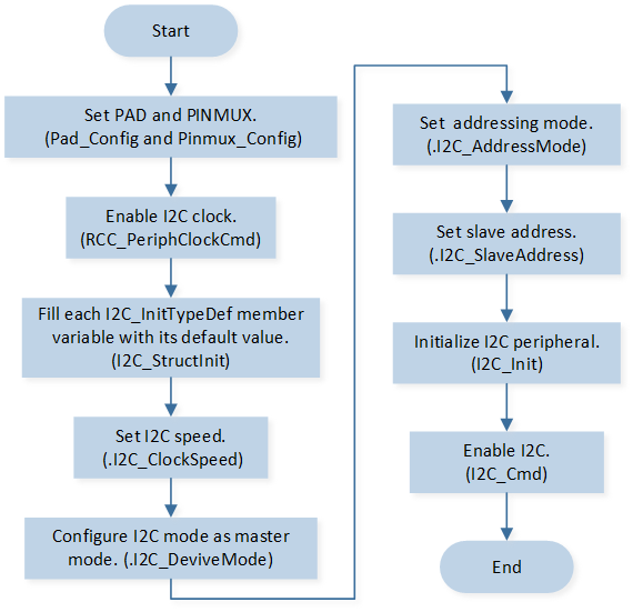
I2C Master Mode Initialization Flow Chart
-
Call
Pad_Config()andPinmux_Config()to initialize the pin.static void board_i2c0_init(void) { Pinmux_Config(PIN_I2C0_SDA, I2C0_DAT); Pinmux_Config(PIN_I2C0_SCL, I2C0_CLK); Pad_Config(PIN_I2C0_SDA, PAD_PINMUX_MODE, PAD_IS_PWRON, PAD_PULL_NONE, PAD_OUT_ENABLE, PAD_OUT_HIGH); Pad_Config(PIN_I2C0_SCL, PAD_PINMUX_MODE, PAD_IS_PWRON, PAD_PULL_NONE, PAD_OUT_ENABLE, PAD_OUT_HIGH); }
Call
RCC_PeriphClockCmd()to enable the I2C clock and function.-
Initialize the I2C peripheral:
Define the
I2C_InitTypeDeftypeI2C_InitStructure, and callI2C_StructInit()to pre-fillI2C_InitStructurewith default values.Modify the
I2C_InitStructureparameters as needed. The I2C initialization parameter configuration is shown in the table below.Call
I2C_Init()to initialize the I2C peripheral.
I2C Initialization Parameters I2C Hardware Parameters
Setting in the
I2C_InitStructureI2C
Clock
100000
Device Role (I2C Master or I2C Slave)
Address Mode (7bits/10bits Mode)
Slave Address
0x50
Auto ACK Enable
Call
I2C_INTConfig()to enable stop signal detection interruptI2C_INT_STOP_DET.Call
NVIC_Init()to enable NVIC of I2C.Call
I2C_Cmd()to enable I2C.
Functional Implementation
Master Repeat Read
The master call I2C_RepeatRead(), sends the data in I2C_WriteBuf to the slave, and reads back the data sent by the slave into I2C_ReadBuf.
uint8_t I2C_WriteBuf[16] = {0xaa, 0xbb, 0x66, 0x68, 0x77, 0x88};
uint8_t I2C_ReadBuf[16] = {0, 0, 0, 0};

I2C_RepeatRead(I2C0, I2C_WriteBuf, 2, I2C_ReadBuf, 4);
Interrupt Handle
When the master detects a stop signal, stop signal detection interrupt will be triggered and enters the interrupt handler:
Call
I2C_GetINTStatus()to checkI2C_INT_STOP_DETinterrupt status.Call
I2C_ClearINTPendingBit()to clearI2C_INT_STOP_DETinterrupt.