Software Accelerate
Overall Flow Chart
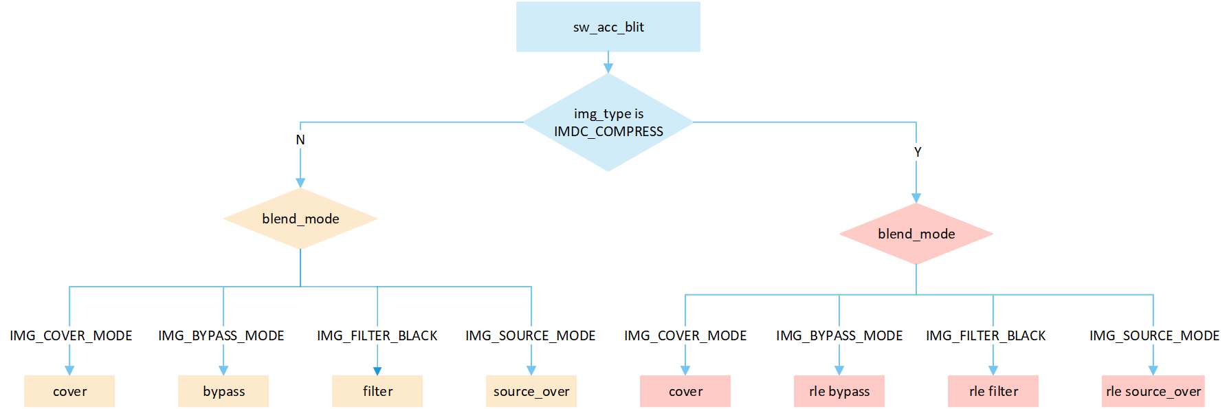
The flowchart depicts the image resource processing flow accelerated by software. When processing images, different processing methods are selected based on the compression status and type of image:
Cover: Write the source image data directly to the corresponding position in the frame buffer. Do not perform any processing, just overwrite it.
Bypass: Write the source image data directly to the corresponding position in the frame buffer. Bypass mode is incapable of handling the transparency of images. It applies a global opacity value to the entire image, thereby affecting the overall transparency. When it comes to creating transparency effects, bypass mode is more space-efficient compared to source_over mode.
Filter black: The filtering technique effectively sifts out pixel data with a value of zero from the originating image data, which essentially means that black pixels are precluded from being inscribed into the frame buffer. This mechanism induces much swifter refresh dynamics. Pixels of any color other than black undergo the standard processing method and are duly recorded into the frame buffer.
Source_over: A blending method that combines image color data and frame buffer pixel color data to calculate the final color based on the opacity_value value
Sa, and writes it to the corresponding location in the frame buffer. The formula is((255 - Sa) * D + Sa * S) / 255), whereSais the opacity_value of the original image,Dis the frame buffer pixel data, andSis the source image pixel data.
The
img_typecan be obtained from theheadof the image, where the structure of the image head is as follows.
typedef struct gui_rgb_data_head
{
    unsigned char scan : 1;
    unsigned char align : 1;
    unsigned char resize: 2; //0-no resize;1-50%(x&y);2-70%;3-80%
    unsigned char compress: 1;
    unsigned char rsvd : 3;
    char type;
    short w;
    short h;
    char version;
    char rsvd2;
} gui_rgb_data_head_t;
The value of
img_typeis depicted in the enum below. If the value isIMDC_COMPRESS, it indicates that the image is compressed and enters therleprocessing flow; otherwise, it enters theno rleprocessing flow.
typedef enum
{
    RGB565      = 0, //bit[4:0] for Blue, bit[10:5] for Green, bit[15:11] for Red
    ARGB8565    = 1, //bit[4:0] for Blue, bit[10:5] for Green, bit[15:11] for Red, bit[23:16] for Alpha
    RGB888      = 3, //bit[7:0] for Blue, bit[15:8] for Green, bit[23:16] for Red
    ARGB8888    = 4, //bit[7:0] for Blue, bit[15:8] for Green, bit[23:16] for Red, bit[21:24] for Alpha
    BINARY      = 5,
    ALPHAMASK   = 9,
    BMP         = 11,
    JPEG        = 12,
    PNG         = 13,
    GIF         = 14,
    RTKARGB8565 = 15,
} GUI_FormatType;
Execute the corresponding
blitprocess based on differentblend_mode.
typedef enum
{
    IMG_BYPASS_MODE = 0,
    IMG_FILTER_BLACK,
    IMG_SRC_OVER_MODE, //S * Sa + (1 - Sa) * D
    IMG_COVER_MODE,
    IMG_RECT,
} BLEND_MODE_TYPE;
When the image is compressed, it is necessary to obtain the compression header from the address of the compressed data. The
algorithm_typeparameter of this header contains the actual image type. The types of compressed images are described in theimdc_src_typestruct, which includes three types:IMDC_SRC_RGB565,IMDC_SRC_RGB888, andIMDC_SRC_ARGB8888.
typedef struct imdc_file_header
{
    struct
    {
        uint8_t algorithm: 2;
        uint8_t feature_1: 2;
        uint8_t feature_2: 2;
        uint8_t pixel_bytes: 2;
    } algorithm_type;
    uint8_t reserved[3];
    uint32_t raw_pic_width;
    uint32_t raw_pic_height;
} imdc_file_header_t;
typedef enum
{
    IMDC_SRC_RGB565 = 0x04, // 4,
    IMDC_SRC_RGB888 = 0x44, // 68,
    IMDC_SRC_ARGB8888 = 0x84, // 132,

} imdc_src_type;
Overview No RLE Cover Mode
The following flow describes the cover mode process for No RLE compressed image. Select a processing method based on the image matrix and the pixel byte of the display device, and write it to the frame buffer.
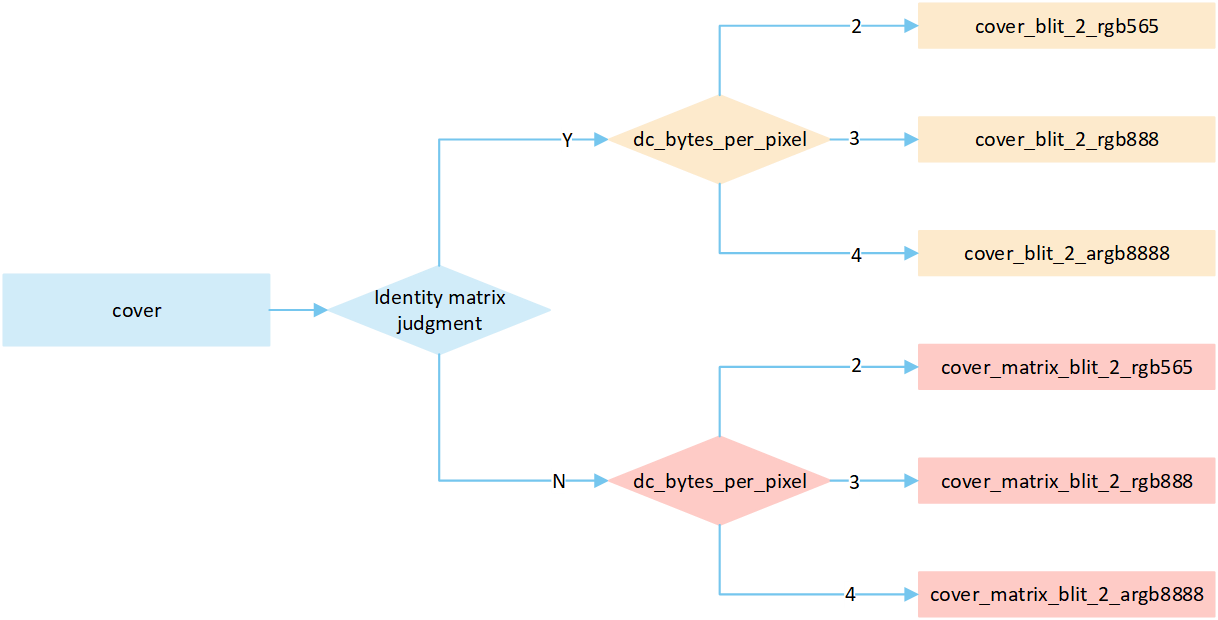
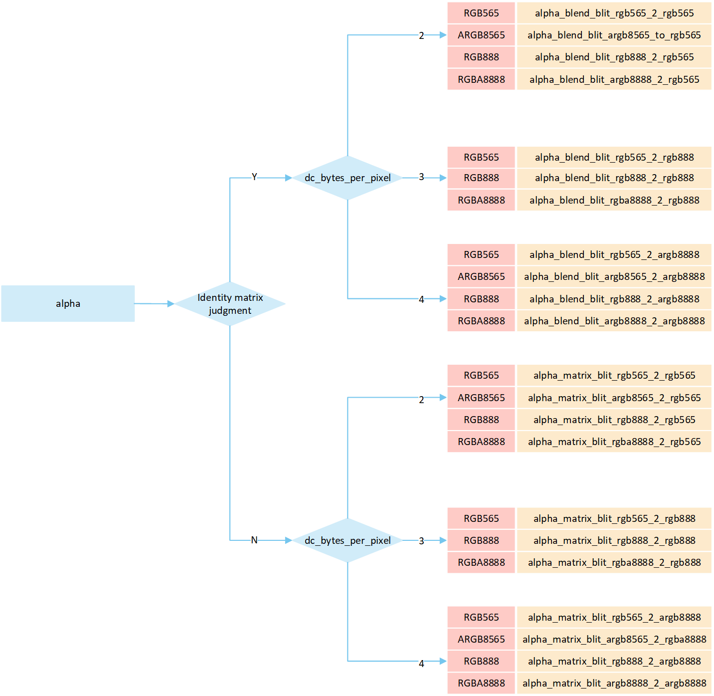
If the matrix is an identity matrix, a blit process without matrix operations is performed; otherwise, a blit process with matrix operations is carried out.
The
dc_bytes_per_pixelis pixel bytes of display device, calculated asdc->bit_depth >> 3, wherebit_depthis the bit depth of the display device. Taking a display device with a bit depth of 24 as an example, its pixel bytes are 3.
No RLE Cover
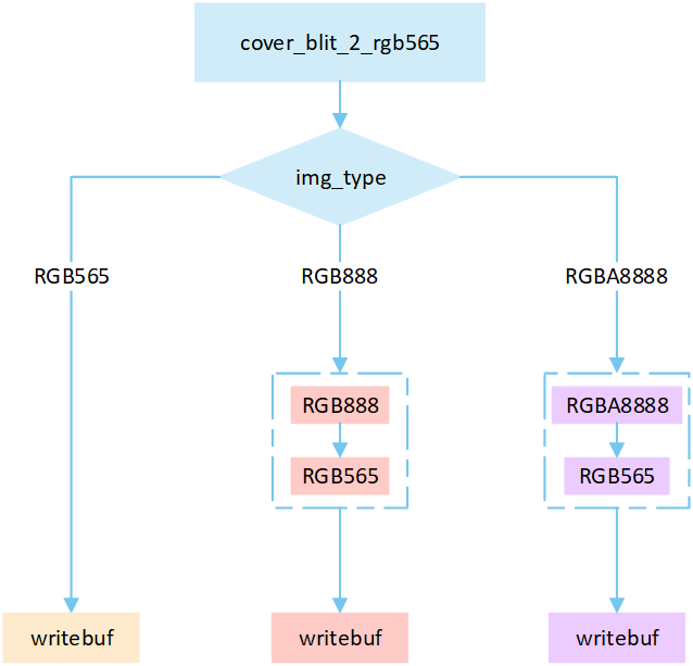
The following flowchart describes the process of writing uncompressed images to a frame buffer in cover mode. Taking the target device image type as RGB565 as an example.
No RLE Cover Matrix
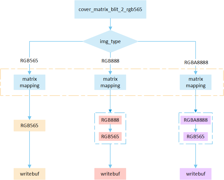
The following flowchart describes the process of writing uncompressed images to a frame buffer using cover mode with matrix operations. Taking the target device image type as RGB565 as an example.
Overview No RLE Bypass Mode
The following flow describes the bypass mode process for No RLE compressed image. Select a processing method based on the image matrix and the pixel byte of the display device, and write it to the frame buffer.
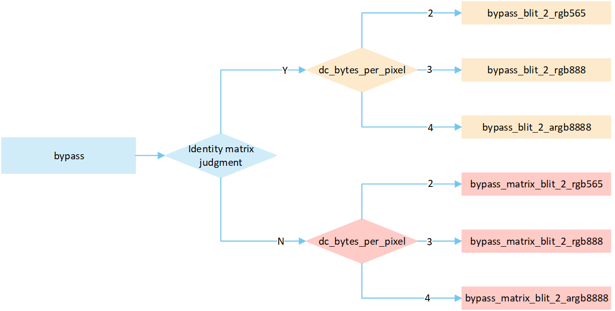
If the matrix is an identity matrix, a blit process without matrix operations is performed; otherwise, a blit process with matrix operations is carried out.
The
dc_bytes_per_pixelis pixel bytes of display device, calculated asdc->bit_depth >> 3, wherebit_depthis the bit depth of the display device. Taking a display device with a bit depth of 24 as an example, its pixel bytes are 3.
No RLE Bypass Mode
The following flowchart describes the process of writing uncompressed images to a frame buffer in bypass mode. Taking the target device image type as RGB565 as an example.
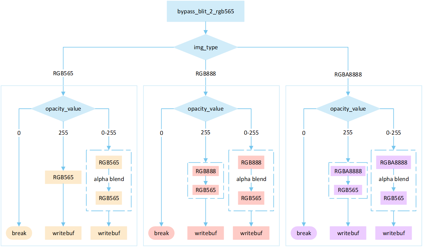
Perform different processing steps based on the
img_type.Based on the
opacity_value, execute the corresponding operation to write image pixels into the framebuffer.If the
opacity_valueis0, the image is not displayed and the process is break.If the
opacity_valueis255, convert the source image pixels to RGB565 format and write them to the frame buffer.If the
opacity_valueis between0 and 255, perform an alpha blending operation to blend the source image pixels with the corresponding frame buffer pixels. The blending formula is((255 - Sa) * D + Sa * S) / 255). Write the blended result to the frame buffer.
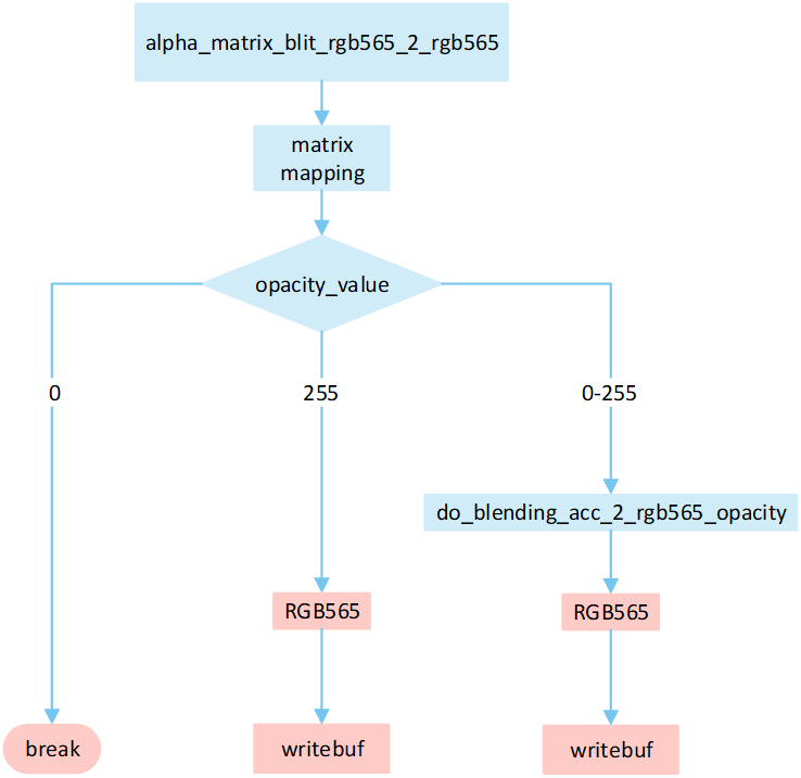
No RLE Bypass Matrix
The following flowchart describes the process of writing uncompressed images to a frame buffer using blend mode with matrix operations. Taking the target device image type as RGB565 as an example.
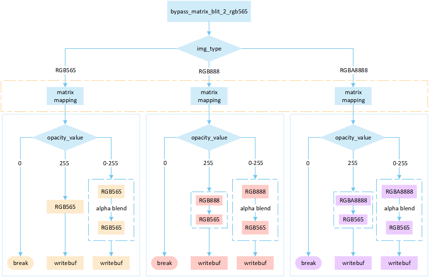
Perform different processing steps based on the
img_type.Perform matrix calculation to map the target area write-in points to image pixels, and obtain the pixel value of the image pixels.
Based on the
opacity_value, execute the corresponding operation to write image pixels into the framebuffer.If the
opacity_valueis0, the image is not displayed and the process is break.If the
opacity_valueis255, convert the source image pixels to RGB565 format and write them to the frame buffer.If the
opacity_valueis between0 and 255, perform an alpha blending operation to blend the source image pixels with the corresponding frame buffer pixels. The blending formula is((255 - Sa) * D + Sa * S) / 255). Write the blended result to the frame buffer.
Overview No RLE Filter
The following flow describes the filter mode process for No RLE compressed image. Select a processing method based on the image matrix and the pixel byte of the display device, and write it to the frame buffer.
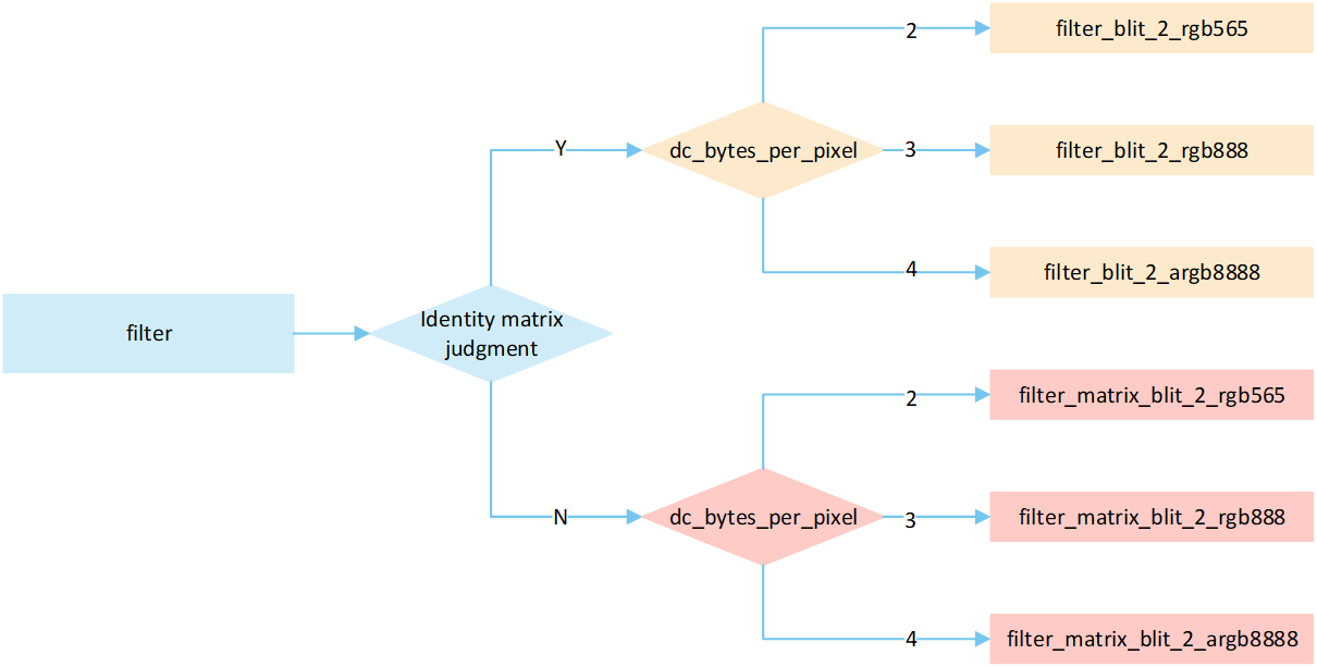
No RLE Filter
The following flowchart describes the process of writing uncompressed images to a frame buffer using filter mode. Taking the target device image type as RGB565 as an example.
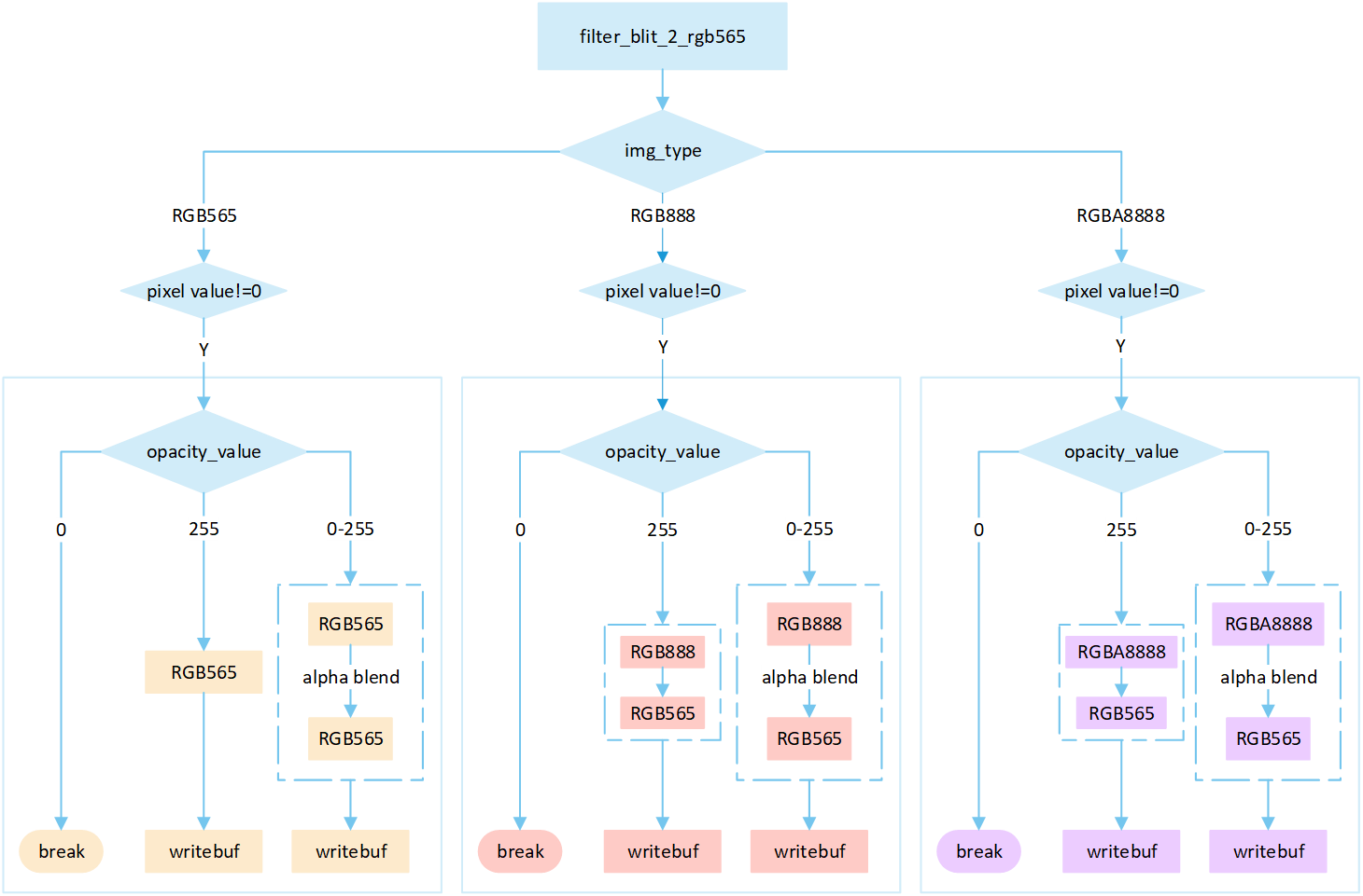
Perform different processing steps based on the
img_type.If the pixel value is 0, skip the processing; otherwise, perform the subsequent writing operation.
Based on the
opacity_value, execute the corresponding operation to write image pixels into the framebuffer.If the
opacity_valueis0, the image is not displayed and the process is break.If the
opacity_valueis255, convert the source image pixels to RGB565 format and write them to the frame buffer.If the
opacity_valueis between0 and 255, perform an alpha blending operation to blend the source image pixels with the corresponding frame buffer pixels. The blending formula is((255 - Sa) * D + Sa * S) / 255). Write the blended result to the frame buffer.
No RLE Filter Matrix
The following flowchart describes the process of writing uncompressed images to a frame buffer using filter mode with matrix operations. Taking the target device image type as RGB565 as an example.
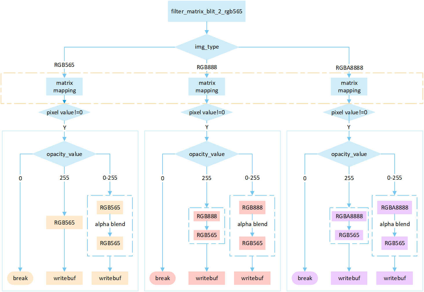
Perform different processing steps based on the
img_type.Perform matrix calculation to map the target area write-in points to image pixels, and obtain the pixel value of the image pixels.
If the pixel value is 0, skip the processing; otherwise, perform the subsequent writing operation.
Based on the
opacity_value, execute the corresponding operation to write image pixels into the framebuffer.If the
opacity_valueis0, the image is not displayed and the process is break.If the
opacity_valueis255, convert the source image pixels to RGB565 format and write them to the frame buffer.If the
opacity_valueis between0 and 255, perform an alpha blending operation to blend the source image pixels with the corresponding frame buffer pixels. The blending formula is((255 - Sa) * D + Sa * S) / 255). Write the blended result to the frame buffer.
Overview No RLE Source_over
The following flow describes the source_over mode process for No RLE compressed image. Select a processing method based on the image matrix and the pixel byte of the display device, and write it to the frame buffer.
No RLE Alpha No Matrix
The following flowchart describes the process of writing uncompressed images to a frame buffer using source_over mode. Taking the target device image type as RGB565 and the source image type as RGB565 as an example.
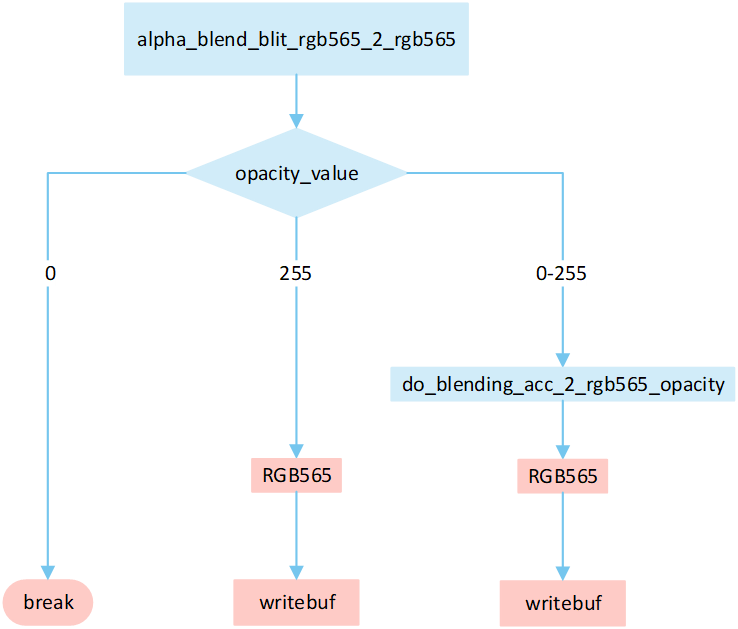
Based on the opacity_value, execute the corresponding operation to write image pixels into the framebuffer.
If the
opacity_valueis0, the image is not displayed and the process is break.If the
opacity_valueis255, convert the source image pixels to RGB565 format and write them to the frame buffer.If the
opacity_valueis between0 and 255, performdo_blending_acc_2_rgb565_opacityto blend the source image pixels with the corresponding frame buffer pixels. Write the blended result to the frame buffer.
No RLE Alpha Matrix
The following flowchart describes the process of writing uncompressed images to a frame buffer using source_over mode with matrix operations. Taking the target device image type as RGB565 and the source image type as RGB565 as an example.
Perform matrix calculation to map the target area write-in points to image pixels, and obtain the pixel value of the image pixels.
Based on the
opacity_value, execute the corresponding operation to write image pixels into the framebuffer.If the
opacity_valueis0, the image is not displayed and the process is break.If the
opacity_valueis255, convert the source image pixels to RGB565 format and write them to the frame buffer.If the
opacity_valueis between0 and 255, performdo_blending_acc_2_rgb565_opacityto blend the source image pixels with the corresponding frame buffer pixels. Write the blended result to the frame buffer.
Overview RLE Cover Mode
The following flow describes the cover mode process for RLE compressed image. Select a processing method based on the image matrix and the pixel byte of the display device, and write it to the frame buffer.
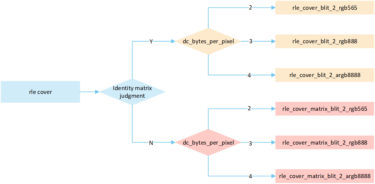
RLE Cover No Matrix
The following flowchart describes the process of writing compressed images to a frame buffer in cover mode. Taking the target device image type as RGB565 as an example.
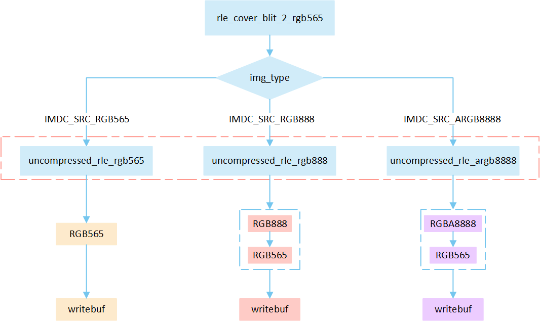
Perform different processing steps based on the
img_typefrom the head of compression data.Decompress the compressed image data.
Write the pixel result to the frame buffer.
RLE Cover Matrix
The following flowchart describes the process of writing compressed images to a frame buffer in cover mode with matrix operations. Taking the target device image type as RGB565 as an example.
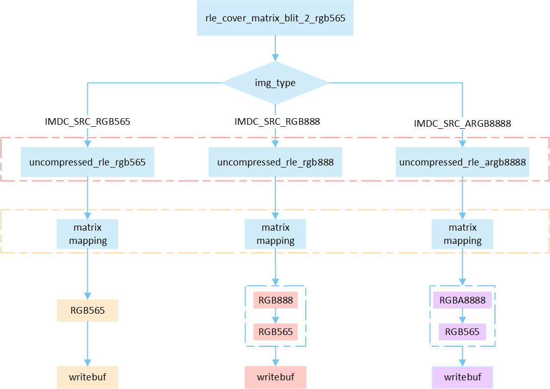
Perform different processing steps based on the
img_typefrom the head of compression data.Decompress the compressed image data.
Perform matrix calculation to map the target area write-in points to image pixels, and obtain the pixel value of the image pixels.
Write the pixel result to the frame buffer.
Overview RLE Bypass Mode
The following flow describes the bypass mode process for RLE compressed image. Select a processing method based on the image matrix and the pixel byte of the display device, and write it to the frame buffer.
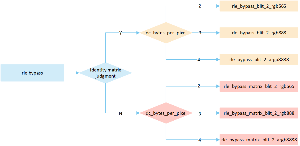
RLE Bypass No Matrix
The following flowchart describes the process of writing compressed images to a frame buffer in bypass mode. Taking the target device image type as RGB565 as an example.
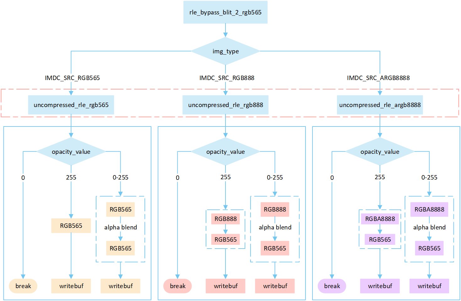
Perform different processing steps based on the
img_typefrom the head of compression data.Decompress the compressed image data.
Based on the
opacity_value, execute the corresponding operation to write image pixels into the framebuffer.If the
opacity_valueis0, the image is not displayed and the process is break.If the
opacity_valueis255, convert the source image pixels to RGB565 format and write them to the frame buffer.If the
opacity_valueis between0 and 255, perform an alpha blending operation to blend the source image pixels with the corresponding frame buffer pixels. The blending formula is((255 - Sa) * D + Sa * S) / 255). Write the blended result to the frame buffer.
RLE Bypass Matrix
The following flowchart describes the process of writing compressed images to a frame buffer in bypass mode with matrix operations. Taking the target device image type as RGB565 as an example.
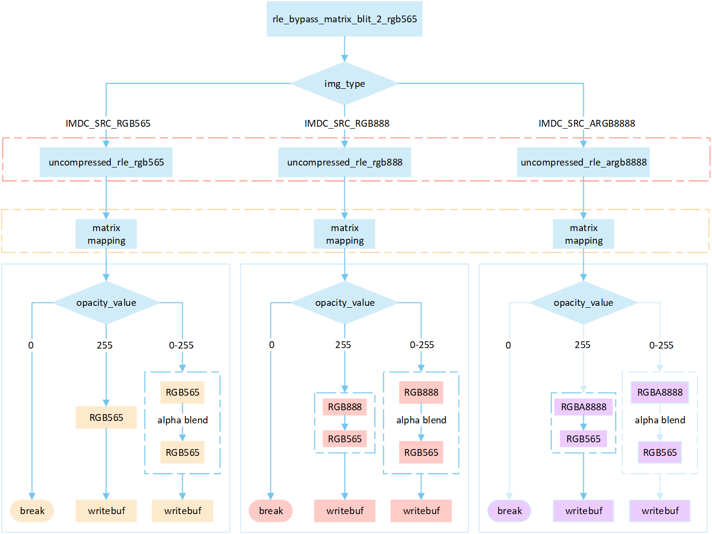
Perform different processing steps based on the
img_typefrom the head of compression data.Decompress the compressed image data.
Perform matrix calculation to map the target area write-in points to image pixels, and obtain the pixel value of the image pixels.
Based on the
opacity_value, execute the corresponding operation to write image pixels into the framebuffer.If the
opacity_valueis0, the image is not displayed and the process is break.If the
opacity_valueis255, convert the source image pixels to RGB565 format and write them to the frame buffer.If the
opacity_valueis between0 and 255, perform an alpha blending operation to blend the source image pixels with the corresponding frame buffer pixels. The blending formula is((255 - Sa) * D + Sa * S) / 255). Write the blended result to the frame buffer.
Overview RLE Filter
The following flow describes the filter mode process for RLE compressed image. Select a processing method based on the image matrix and the pixel byte of the display device, and write it to the frame buffer.
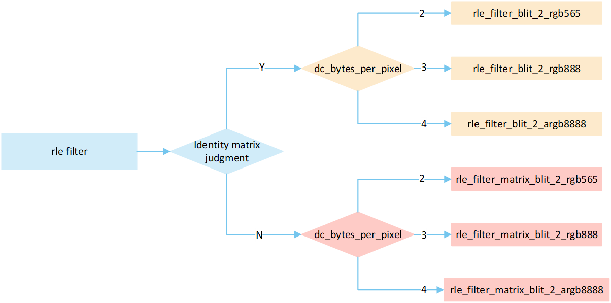
RLE Filter
The following flowchart describes the process of writing compressed images to a frame buffer in filter mode. Taking the target device image type as RGB565 as an example.
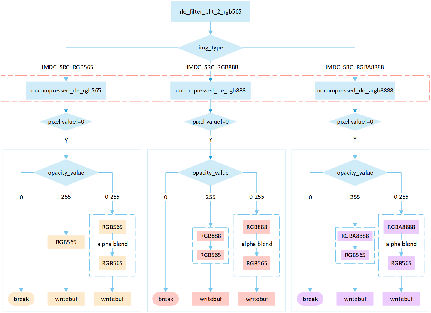
Perform different processing steps based on the
img_typefrom the head of compression data.Decompress the compressed image data.
If the pixel value is 0, skip the processing; otherwise, perform the subsequent writing operation.
Based on the
opacity_value, execute the corresponding operation to write image pixels into the framebuffer.If the
opacity_valueis0, the image is not displayed and the process is break.If the
opacity_valueis255, convert the source image pixels to RGB565 format and write them to the frame buffer.If the
opacity_valueis between0 and 255, perform an alpha blending operation to blend the source image pixels with the corresponding frame buffer pixels. The blending formula is((255 - Sa) * D + Sa * S) / 255). Write the blended result to the frame buffer.
RLE Filter Matrix
The following flowchart describes the process of writing compressed images to a frame buffer in filter mode with matrix operations. Taking the target device image type as RGB565 as an example.
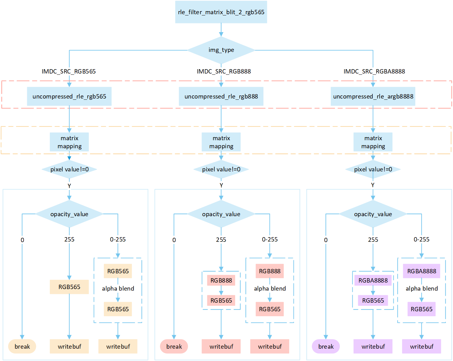
Perform different processing steps based on the
img_typefrom the head of compression data.Decompress the compressed image data.
Perform matrix calculation to map the target area write-in points to image pixels, and obtain the pixel value of the image pixels.
If the pixel value is 0, skip the processing; otherwise, perform the subsequent writing operation.
Based on the
opacity_value, execute the corresponding operation to write image pixels into the framebuffer.If the
opacity_valueis0, the image is not displayed and the process is break.If the
opacity_valueis255, convert the source image pixels to RGB565 format and write them to the frame buffer.If the
opacity_valueis between0 and 255, perform an alpha blending operation to blend the source image pixels with the corresponding frame buffer pixels. The blending formula is((255 - Sa) * D + Sa * S) / 255). Write the blended result to the frame buffer.
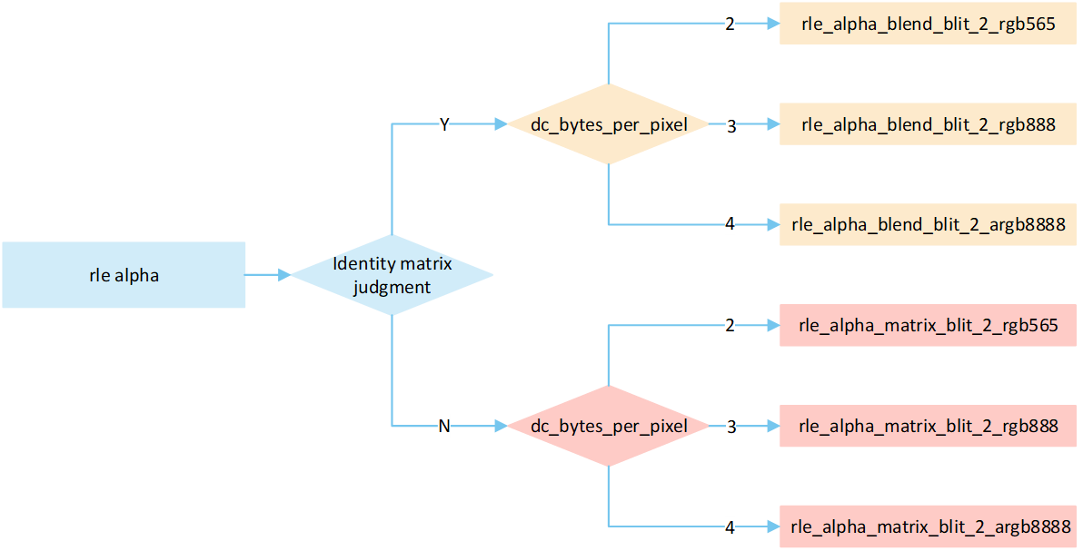
Overview RLE Source_over
The following flow describes the source_over mode process for RLE compressed image. Select a processing method based on the image matrix and the pixel byte of the display device, and write it to the frame buffer.
RLE Source_over No Matrix
The following flowchart describes the process of writing compressed images to a frame buffer in source_over mode. Taking the target device image type as RGB565 as an example.
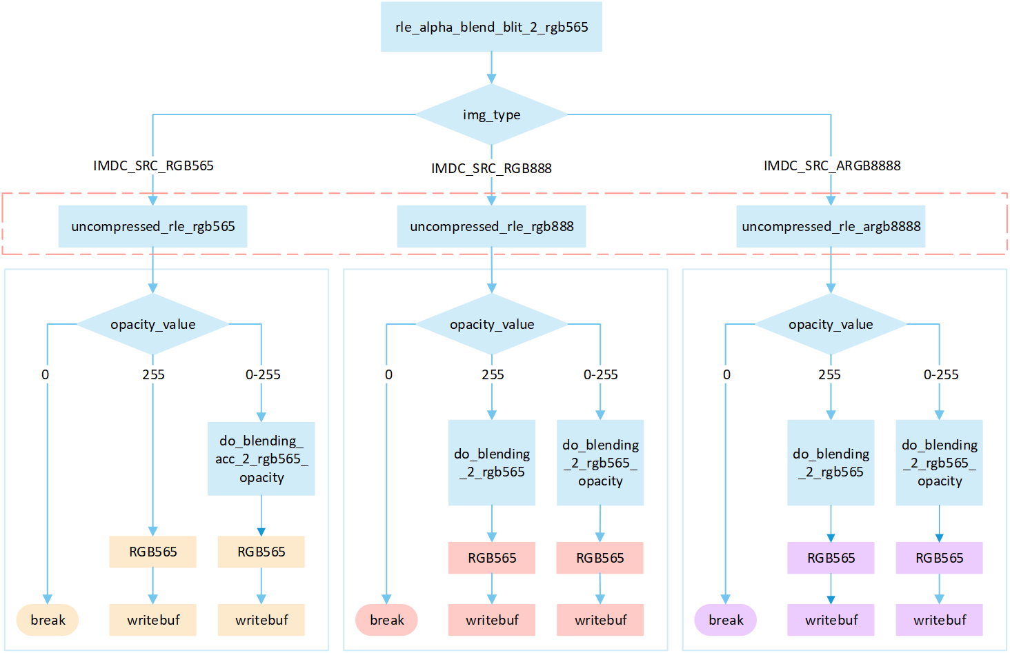
Perform different processing steps based on the
img_typefrom the head of compression data.Decompress the compressed image data.
Based on the
opacity_value, execute the corresponding operation to write image pixels into the framebuffer.If the
opacity_valueis0, the image is not displayed and the process is break.If the
opacity_valueis255: When the source image is in RGB565 format, directly write it to the frame buffer. Otherwise, perform the correspondingdo blendoperation and write the blend result to the frame buffer.If the
opacity_valueis between0 and 255, perform the appropriatedo_blendingoperation to blend the source image pixels with the corresponding frame buffer pixels. Write the blended result to the frame buffer.
RLE Source_over Matrix
The following flowchart describes the process of writing compressed images to a frame buffer in source_over mode with matrix operations. Taking the target device image type as RGB565 as an example.
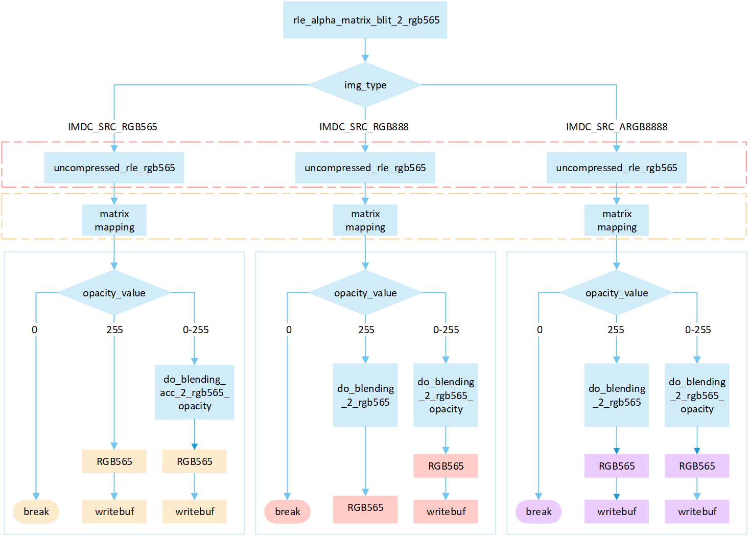
Perform different processing steps based on the
img_typefrom the head of compression data.Decompress the compressed image data.
Perform matrix calculation to map the target area write-in points to image pixels, and obtain the pixel value of the image pixels.
Based on the
opacity_value, execute the corresponding operation to write image pixels into the framebuffer.If the
opacity_valueis0, the image is not displayed and the process is break.If the
opacity valuelevel is255: When the source image is in RGB565 format, directly write it to the frame buffer. Otherwise, perform the correspondingdo blendoperation and write the blend result to the frame buffer.If the
opacity_valueis between0 and 255, perform the appropriatedo_blendingoperation to blend the source image pixels with the corresponding frame buffer pixels. Write the blended result to the frame buffer.
Flowchart download
If you need to modify the vision file of the flowchart, please download it from the following path. acc rle no rle
Note
In compressed source_over matrix mode output rle_rgb888 and rle_rgba8888 equivalent to output as rle_rgb565.
Support Input type and Output type
Input type |
Output type |
|---|---|
RGB565 |
RGB565 |
RGB888 |
RGB888 |
- |
ARGB8565 |
ARGB8888 |
ARGB8888 |