Input Interrupt
This sample uses the GPIO input function to detect the GPIO input signal by interrupt.
It is necessary to configure the GPIO to input mode and enable the interrupt function. When the input signal changes, it will trigger the GPIO interrupt, and the input level information will be printed in the interrupt handler.
Users can modify pin information through different macro configurations. For specific macro configurations, refer to Configurations.
Requirements
For hardware requirements, please refer to the Requirements.
Configurations
-
The following macros can be configured to modify GPIO pin definitions.
#define GPIO_DEMO_INPUT_PIN0                      P1_0
#define GPIO_DEMO_INPUT_PIN1                      P1_1
#define GPIO_DEMO_INPUT_PIN2                      P2_1
#define GPIO_DEMO_INPUT_PIN3                      P2_2
-
The entry function is as follows, call this function in
main()to run this sample code. For more details, please refer to the Initialization.gpio_int_demo();
Building and Downloading
For building and downloading, please refer to the Building and Downloading.
Experimental Verification
-
Press the Reset button on the EVB and the message will be displayed in the Debug Analyzer.
gpio_int_demo -
When a low level input is detected on
P1_0, the following message is printed in the Debug Analyzer.gpio_isr_cb: pin_name P1_0, gpio_level 0
Code Overview
This section introduces the code and process description for initialization and corresponding function implementation in the sample.
Source Code Directory
The directory for project file and source code are as follows.
For project directory, please refer to Source Code Directory.
Source code directory:
sdk\sample\io_demo\gpio\interrupt\gpio_int_demo.c.
Initialization
The initialization flow for peripherals can refer to Initialization Flow.
The GPIO initialization flow is shown in the following figure.
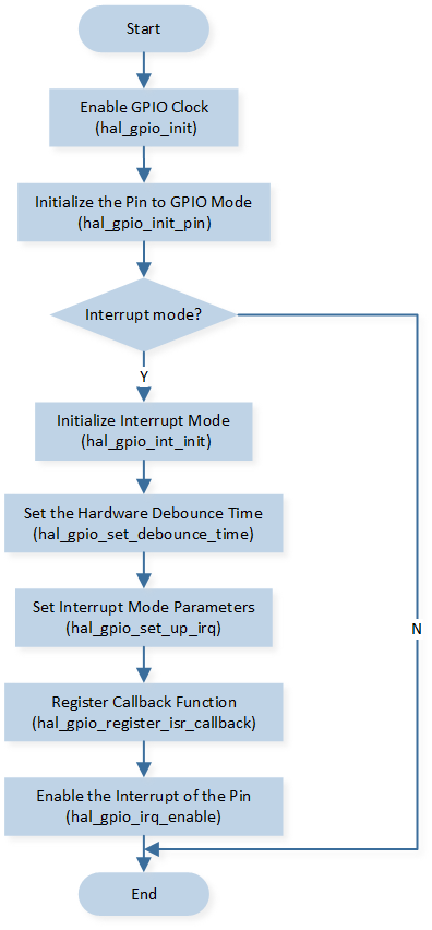
GPIO Initialization Flow Chart
-
Call
hal_gpio_init()to enable GPIO clock.hal_gpio_init();
-
Call
hal_gpio_int_init()to initialize GPIO interrupt.hal_gpio_int_init();
-
Call
hal_gpio_set_debounce_time()to set GPIO debounce time.hal_gpio_set_debounce_time(30);
Call
hal_gpio_init_pin()to initialize the GPIO peripheral and callhal_gpio_set_up_irq()to initialize interrupt-related parameters. The GPIO initialization parameters are configured as shown in the table below.
GPIO Hardware Parameters |
GPIO |
|---|---|
Pin Number |
|
GPIO Type |
|
GPIO Mode |
|
GPIO Pull Value |
|
Interrupt Type |
|
Interrupt Polarity |
|
Debounce Enable |
|
GPIO Hardware Parameters |
GPIO |
|---|---|
Pin Number |
|
GPIO Type |
|
GPIO Mode |
|
GPIO Pull Value |
|
Interrupt Type |
|
Interrupt Polarity |
|
Debounce Enable |
|
GPIO Hardware Parameters |
GPIO |
|---|---|
Pin Number |
|
GPIO Type |
|
GPIO Mode |
|
GPIO Pull Value |
|
Interrupt Type |
|
Interrupt Polarity |
|
Debounce Enable |
|
GPIO Hardware Parameters |
GPIO |
|---|---|
Pin Number |
|
GPIO Type |
|
GPIO Mode |
|
GPIO Pull Value |
|
Interrupt Type |
|
Interrupt Polarity |
|
Debounce Enable |
|
Call
hal_gpio_register_isr_callback()to register gpio interrupt callback.Call
hal_gpio_irq_enable()to enable gpio interrupt.
Functional Implementation
When connecting P1_0 to GND (a falling edge on P1_0), detecting a falling edge of P1_0 triggers a GPIO interrupt.
The interrupt handler function gpio_isr_cb prints interrupt information.
static void gpio_isr_cb(uint32_t context)
{
    uint8_t pin_index = (uint32_t)context;
    T_GPIO_LEVEL gpio_level = hal_gpio_get_input_level(pin_index);

    IO_PRINT_INFO2("gpio_isr_cb: pin_name %s, gpio_level %d", TRACE_STRING(Pad_GetPinName(pin_index)),
                   gpio_level);

    if (gpio_level == GPIO_LEVEL_LOW)
    {
        hal_gpio_irq_change_polarity(pin_index, GPIO_IRQ_ACTIVE_HIGH);
    }
    else
    {
        hal_gpio_irq_change_polarity(pin_index, GPIO_IRQ_ACTIVE_LOW);
    }
}