Output
This example is based on the output function of GPIO, implementing periodic state toggle control of the LED.
Configure the GPIO as output mode. Within the while loop, toggle the output level every 1 second to drive the LED to blink.
Users can modify pin information through different macro configurations. For specific macro configurations, refer to Configurations.
Requirements
For hardware requirements, please refer to the Requirements.
Wiring
On EVB, connect P0_1 and LED1, connect P0_2 and LED2, connect P0_3 and LED3.
The hardware connection of GPIO output sample code is shown in the figure below.
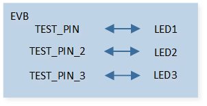
GPIO Output Sample Code Hardware Connection Diagram
Configurations
-
The following macros can be configured to modify GPIO pin definitions.
#define TEST_PIN            P0_1
#define TEST_PIN_2          P0_2
#define TEST_PIN_3          P0_3
-
The entry function is as follows, call this function in
main()to run this sample code. For more details, please refer to the Initialization.gpio_output_demo();
Building and Downloading
For building and downloading, please refer to the Building and Downloading.
Experimental Verification
-
Press the Reset button on the EVB and the message will be displayed in the Debug Analyzer.
gpio_output_demo: start
Code Overview
This section introduces the code and process description for initialization and corresponding function implementation in the sample.
Source Code Directory
The directory for project file and source code are as follows.
For project directory, please refer to Source Code Directory.
Source code directory:
sdk\sample\io_demo\gpio\output\gpio_output_demo.c.
Initialization
The initialization flow for peripherals can refer to Initialization Flow.
-
Call
hal_gpio_init()to enable GPIO clock.hal_gpio_init();
Call
hal_gpio_init_pin()to initialize the GPIO peripheral. The GPIO initialization parameters are configured as shown in the table below.
GPIO Hardware Parameters |
GPIO |
|---|---|
Pin Number |
|
GPIO Type |
|
GPIO Mode |
|
GPIO Pull Value |
GPIO Hardware Parameters |
GPIO |
|---|---|
Pin Number |
|
GPIO Type |
|
GPIO Mode |
|
GPIO Pull Value |
GPIO Hardware Parameters |
GPIO |
|---|---|
Pin Number |
|
GPIO Type |
|
GPIO Mode |
|
GPIO Pull Value |
Call
hal_gpio_set_level()to output high level.
Functional Implementation
After initialization, call hal_gpio_set_level() within the while loop to control the GPIO output high and low levels.
for (uint16_t i = 0; i < 10; i++)
{
    platform_delay_ms(1000);
    hal_gpio_set_level(TEST_PIN, GPIO_LEVEL_LOW);
    hal_gpio_set_level(TEST_PIN_2, GPIO_LEVEL_LOW);
    hal_gpio_set_level(TEST_PIN_3, GPIO_LEVEL_LOW);
    platform_delay_ms(1000);
    hal_gpio_set_level(TEST_PIN, GPIO_LEVEL_HIGH);
    hal_gpio_set_level(TEST_PIN_2, GPIO_LEVEL_HIGH);
    hal_gpio_set_level(TEST_PIN_3, GPIO_LEVEL_HIGH);
}