3-Wire SPI
3-Wire SPI Demo Code Support List
The description of 3-wire SPI demo code 1 is shown in the following table.
Demo 1 |
|
|---|---|
Sample Purpose |
Demonstrate how 3-wire SPI single write and read data. |
Brief Introduction |
Use 3-wire SPI for data transmission with PMW3610DM-SUDU mouse sensor. Obtain PMW3610DM-SUDU ID, check whether ID is correct, and print corresponding information in Debug Analyzer. |
File Path |
|
Function Entry |
|
CS Pin Definition |
|
DIO Pin Definition |
|
SCLK Pin Definition |
|
Speed |
800KHz |
Read Delay Time |
2.5us |
Hardware Connection |
As shown in 3-Wire SPI Demo Code 1 Hardware Connection Diagram. Connect M0_0 of EVB to SCLK of sensor, connect M0_1 of EVB to SDIO of sensor, connect M0_2 of EVB to NCS of sensor, connect GND of EVB to GND of sensor, connect U_5V_FT of EVB to 5V of sensor. |
Expected Result |
Press the Reset button on the EVB, if the data transmission is successful, the string spi3wire_demo: Read mouse sensor ID success will be printed in Debug Analyzer; Otherwise, the string spi3wire_demo: Read mouse sensor ID error will be printed in Debug Analyzer. |
The hardware connection of 3-wire SPI demo code 1 is shown in the figure below.
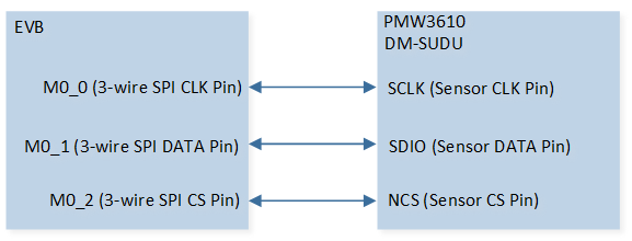
3-Wire SPI Demo Code 1 Hardware Connection Diagram
Functional Overview
3-Wire SPI is used to connect 3-wire SPI interfaces such as CS/DIO/SCLK and has single wire, single/burst read function. It is also possible to adjust the desired delay timing between read/write.
Note
Only RTL87x3D supports 3-wire SPI.
Feature List
Support 2-wire and 3-wire communication.
Support single write and read.
Support burst read.
Configurable delay between write and read.
Data Format
The data contains two bytes, the first byte is the address bit, the highest bit is the read/write control bit, and the second byte is the data byte. As shown below:
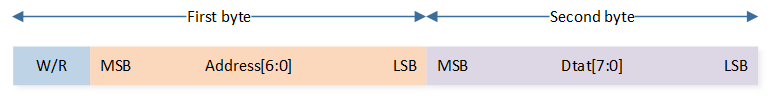
3-Wire SPI Data Format
Write Operation
Write data from the controller to the sensor, only supports single write mode, as shown in the figure below. No delay needs to be added between the address byte and the data byte.
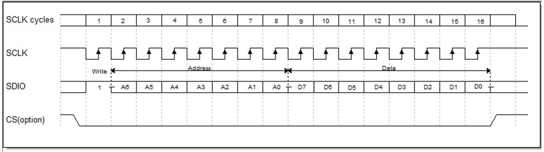
Schematic Diagram of 3-Wire SPI Write Operation Frame Format
Read Operation
Single Read Mode
Between the first byte (address byte) and the second byte (data byte), a delay of ‘T-Hold’ needs to be added. This delay is configured by SPI3WIRE_ReadDelay.
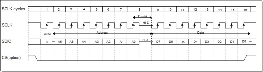
Schematic Diagram of 3-Wire SPI Read Operation Frame Format
Burst Read Mode
In burst read mode, SPI can continuously read multiple bytes of data. Between the first byte (address byte) and the second byte (data byte 0), a delay of ‘T-Hold’ needs to be added. This delay is configured by SPI3WIRE_ReadDelay. There is no delay between the third byte (data byte 1) and the second byte (data byte 0) until the end of a burst read.
Program Examples
Initialization Operation Flow
3-Wire SPI initialization flow is shown in the following figure.
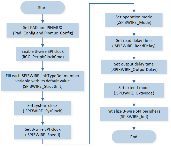
3-Wire SPI Initialization Flow Chart
The codes below demonstrate the 3-wire SPI initialization flow.
/* Enable 3-wire SPI clock */
RCC_PeriphClockCmd(APBPeriph_SPI2W, APBPeriph_SPI2W_CLOCK, ENABLE);

/* Initialize 3-wire SPI */
SPI3WIRE_InitTypeDef SPI3WIRE_InitStruct;
SPI3WIRE_StructInit(&SPI3WIRE_InitStruct);

SPI3WIRE_InitStruct.SPI3WIRE_SysClock       = 20000000;
SPI3WIRE_InitStruct.SPI3WIRE_Speed          = 800000;
SPI3WIRE_InitStruct.SPI3WIRE_Mode           = SPI3WIRE_3WIRE_MODE;
/* delay time = (SPI3WIRE_ReadDelay +1)/(2*SPI3WIRE_Speed). The delay time from the end of address phase to the start of read data phase */
//delay time = (0x03 + 1)/(2 * speed) = 2.5us
SPI3WIRE_InitStruct.SPI3WIRE_ReadDelay      = 0x3;
SPI3WIRE_InitStruct.SPI3WIRE_OutputDelay    = SPI3WIRE_OE_DELAY_NONE;
SPI3WIRE_InitStruct.SPI3WIRE_ExtMode        = SPI3WIRE_NORMAL_MODE;
SPI3WIRE_Init(&SPI3WIRE_InitStruct);
Send Data Operation Flow
3-Wire SPI sends data operation flow is shown in the following figure.
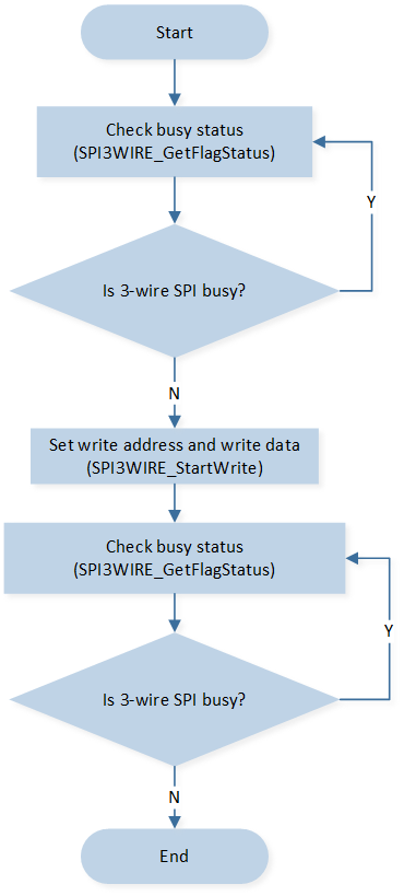
3-Wire SPI Send Data Operation Flow Chart
The codes below demonstrate the 3-wire SPI send data operation flow.
bool Mouse_SingleWrite(uint8_t address, uint8_t data)
{
   uint32_t timeout = 0;

   /* Check SPI busy or not */
   while (SPI3WIRE_GetFlagStatus(SPI3WIRE_FLAG_BUSY) == SET)
   {
      timeout++;
      if (timeout > 0x1ffff)
      {
            return false;
      }
   }

   /* Write data */
   SPI3WIRE_StartWrite(address, data);

   timeout = 0;
   /* Wait for communication to end */
   while (SPI3WIRE_GetFlagStatus(SPI3WIRE_FLAG_BUSY) == SET)
   {
      timeout++;
      if (timeout > 0x1ffff)
      {
            return false;
      }
   }
   return true;
}
Receive Data Operation Flow
3-Wire SPI receives data operation flow is shown in the following figure.
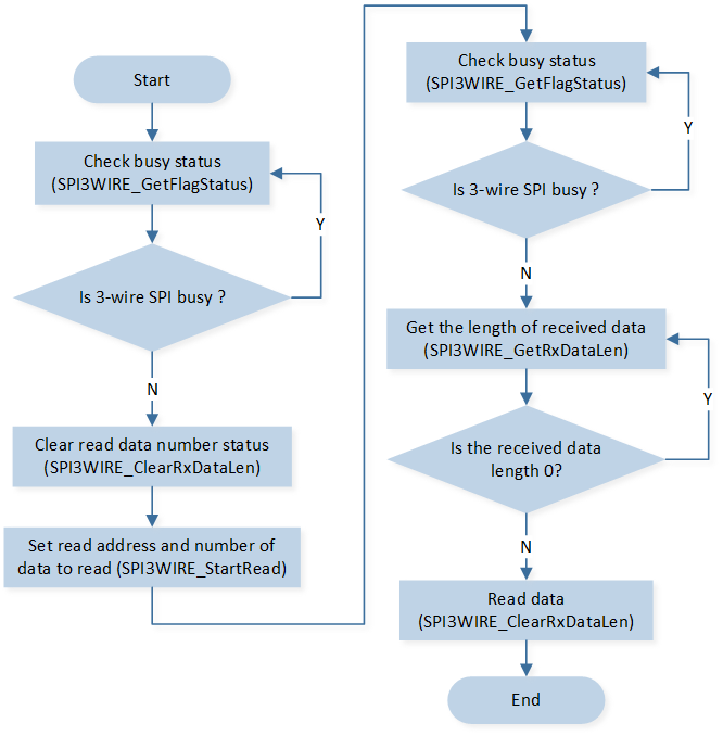
3-Wire SPI Receive Data Operation Flow Chart
The codes below demonstrate the 3-wire SPI receives data operation flow.
uint8_t Mouse_SingleRead(uint8_t address)
{
uint8_t reg_value = 0;
uint32_t timeout = 0;
/* Check SPI busy or not */
while (SPI3WIRE_GetFlagStatus(SPI3WIRE_FLAG_BUSY) == SET)
{
timeout++;
if (timeout > 0x1ffff)
{
break;
}
}
/* Clear Receive data length */
SPI3WIRE_ClearRxDataLen();
SPI3WIRE_StartRead(address, 1);
timeout = 0;
/* Wait for the end of communication */
while (SPI3WIRE_GetFlagStatus(SPI3WIRE_FLAG_BUSY) == SET)
{
timeout++;
if (timeout > 0x1ffff)
{
break;
}
}
/* Get the length of received data */
while (SPI3WIRE_GetRxDataLen() == 0);
/* Read data */
SPI3WIRE_ReadBuf(®_value, 1);
return reg_value;
}