UART
UART Demo Code Support List
This chapter introduces the details of the UART demo code.
UART Demo for Polling Mode
The description of UART demo code 1 is shown in the following table.
Demo 1 |
|
|---|---|
Sample Purpose |
Demonstrate how UART sends and receives data in polling mode. |
Brief Introduction |
This sample code demonstrates the communication between chip and PC. PC transmits some data to chip and then chip returns the same data received to PC. |
File Path |
|
Function Entry |
|
Hardware Connection |
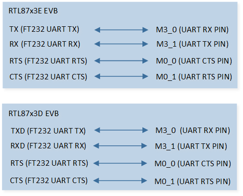
As shown in UART Demo Code 1/2/3/5 Hardware Connection Diagram. RTL87x3E: On EVB, TX is connected to M3_0, RX is connected to M3_1, FT_VIO is connected to VIO1, and CON3 is connected to PC. RTL87x3D: On EVB, TXD is connected to M3_0, RXD is connected to M3_1, FT_VIO is connected to VIO1, and P2 is connected to PC. |
UART TX Pin Definition |
|
UART RX Pin Definition |
|
UART ID |
UART0 |
Baud Rate |
115200 |
Parity Check |
No parity |
Data Format |
8-Bit |
Stop Bit |
1-Bit |
Hardware Flow Control |
None |
Expected Result |
|
The hardware connection of UART demo code 1 is shown in the figure below.

UART Demo Code 1/2/3/5 Hardware Connection Diagram
UART Demo of RX Data in Interrupt Mode
The description of UART demo code 2 is shown in the following table.
Demo 2 |
|
|---|---|
Sample Purpose |
Demonstrate how UART receives data in interrupt mode. |
Brief Introduction |
This sample code demonstrates the communication between chip and PC. PC transmits some data to chip and then chip returns the same data received to PC. |
File Path |
|
Function Entry |
|
Hardware Connection |
As shown in UART Demo Code 1/2/3/5 Hardware Connection Diagram. RTL87x3E: On EVB, TX is connected to M3_0, RX is connected to M3_1, FT_VIO is connected to VIO1, and CON3 is connected to PC. RTL87x3D: On EVB, TXD is connected to M3_0, RXD is connected to M3_1, FT_VIO is connected to VIO1, and P2 is connected to PC. |
UART TX Pin Definition |
|
UART RX Pin Definition |
|
UART ID |
UART0 |
Baud Rate |
115200 |
Parity Check |
No parity |
Data Format |
8-Bit |
Stop Bit |
1-Bit |
Hardware Flow Control |
None |
Expected Result |
|
UART Demo of TX Data in Interrupt Mode
The description of UART demo code 3 is shown in the following table.
Demo 3 |
|
|---|---|
Sample Purpose |
Demonstrate how UART sends data in interrupt mode. |
Brief Introduction |
This sample code demonstrates the communication between chip and PC. Chip transmits some data to PC. |
File Path |
|
Function Entry |
|
Hardware Connection |
As shown in UART Demo Code 1/2/3/5 Hardware Connection Diagram. RTL87x3E: On EVB, TX is connected to M3_0, RX is connected to M3_1, FT_VIO is connected to VIO1, and CON3 is connected to PC. RTL87x3D: On EVB, TXD is connected to M3_0, RXD is connected to M3_1, FT_VIO is connected to VIO1, and P2 is connected to PC. |
UART TX Pin Definition |
|
UART RX Pin Definition |
|
UART ID |
UART0 |
Baud Rate |
115200 |
Parity Check |
No parity |
Data Format |
8-Bit |
Stop Bit |
1-Bit |
Hardware Flow Control |
None |
Expected Result |
Press the Reset button on the EVB, string ### Welcome to use RealTek Bumblebee ###\r\n will be displayed in UART debug tool. |
UART Demo for Hardware Flow Control Function
The description of UART demo code 4 is shown in the following table.
Demo 4 |
|
|---|---|
Sample Purpose |
Demonstrate how UART sends and receives data with hardware flow control. |
Brief Introduction |
This sample code demonstrates the communication between chip and PC. PC transmits some data to chip and then chip returns the same data received to PC. |
File Path |
|
Function Entry |
|
Hardware Connection |
As shown in UART Demo Code 4 Hardware Connection Diagram. RTL87x3E: On EVB, TX is connected to M3_0, RX is connected to M3_1, RTS is connected to M0_0, CTS is connected to M0_1, FT_VIO is connected to VIO1, and CON3 is connected to PC. RTL87x3D: On EVB, TXD is connected to M3_0, RXD is connected to M3_1, RTS is connected to M0_0, CTS is connected to M0_1, FT_VIO is connected to VIO1, and P2 is connected to PC. |
UART TX Pin Definition |
|
UART RX Pin Definition |
|
UART CTS Pin Definition |
|
UART RTS Pin Definition |
|
UART ID |
UART0 |
Baud Rate |
115200 |
Parity Check |
No parity |
Data Format |
8-Bit |
Stop Bit |
1-Bit |
Hardware Flow Control |
CTS and RTS flow control. |
Expected Result |
|
The hardware connection of UART demo code 4 is shown in the figure below.
UART Demo Code 4 Hardware Connection Diagram
UART Demo in DLPS Mode
The description of UART demo code 5 is shown in the following table.
Demo 5 |
|
|---|---|
Sample Purpose |
Demonstrates how UART wakes up the system from DLPS mode. |
Brief Introduction |
This sample code demonstrates the communication between chip and PC.
It realizes the function that transmits and receives data through UART and wakes up the system by UART after entering
DLPS mode. System will enter DLPS mode automatically while it is in idle state. When some data is sent to chip,
|
File Path |
|
Function Entry |
|
Hardware Connection |
As shown in UART Demo Code 1/2/3/5 Hardware Connection Diagram. RTL87x3E: On EVB, TX is connected to M3_0, RX is connected to M3_1, FT_VIO is connected to VIO1, and CON3 is connected to PC. RTL87x3D: On EVB, TXD is connected to M3_0, RXD is connected to M3_1, FT_VIO is connected to VIO1, and P2 is connected to PC. |
UART TX Pin Definition |
|
UART RX Pin Definition |
|
UART ID |
UART2 |
Baud Rate |
115200 |
Parity Check |
No parity |
Data Format |
8-Bit |
Stop Bit |
1-Bit |
Hardware Flow Control |
None |
Expected Result |
|
UART Demo for Adapter One-Wire Mode
The description of UART demo code 6 is shown in the following table.
Demo 6 |
|
|---|---|
Sample Purpose |
Demonstrates how adapter one-wire works. |
Brief Introduction |
This sample code demonstrates how adapter one-wire works. When the adapter plugs in, it works as UART RX. When the adapter plugs out, it works as GPIO. |
File Path |
|
Function Entry |
|
Hardware Connection |
As shown in UART Demo Code 6 Hardware Connection Diagram. On EVB, TX of FT232 is connected to VADP. RTL87x3E: On EVB, the capacitance of ADPIN on PCB needs to be replaced by 100pF. RTL87x3D: The daughter board changes C186 to 100pf. The motherboard removes C164, DP38 and C71, and raises VAUX1 to 3.3V, connecting VIO4 to VAUX1. |
UART RX Pin Definition |
RTL87x3D: |
UART ID |
UART0 |
Baud Rate |
9600 |
Parity Check |
No parity |
Data Format |
8-Bit |
Stop Bit |
1-Bit |
Hardware Flow Control |
None |
Expected Result |
|
The hardware connection of UART demo code 6 is shown in the figure below.
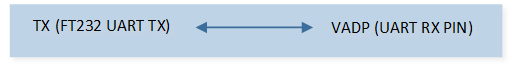
UART Demo Code 6 Hardware Connection Diagram
Functional Overview
UART provides a flexible method for full-duplex data exchange with external devices. The UART utilizes a fractional baud rate generator to provide a wide range of baud rate options. It supports half-duplex single-wire communication. UART can also be used with GDMA to achieve high-speed data communication.
Feature List
Support 1-bit or 2-bit stop bit.
Support 7-bit or 8-bit data format.
Support odd or even parity.
Support hardware flow control.
Programmable baud rate.
Support GDMA.
Support one-wire UART.
Note
RTL87x3D supports 4 UART. RTL87x3E and RTL87x3EP support 3 UART. UART1 is used as log UART.
Data Format
The schematic diagram of the 7-bit data format is shown in the following figure.
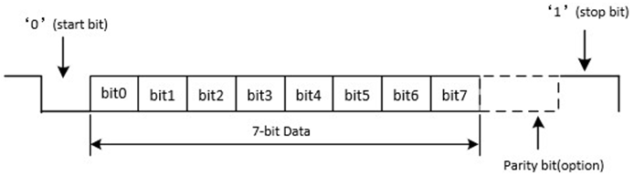
Schematic Diagram of 7-bit Data Format
The schematic diagram of the 8-bit data format is shown in the following figure.
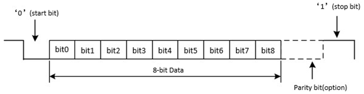
Schematic Diagram of 8-bit Data Format
Parity Check
Odd Parity
Odd parity means that the number of ‘1’ in the data bits and check bit is odd. When the number of ‘1’ in the data bits is odd, the check bit is ‘0’; otherwise, it is ‘1’.
Even Parity
Even parity means that the number of ‘1’ in the data bits and check bit is even. When the number of ‘1’ in the data bits is even, the check bit is ‘0’; otherwise, it is ‘1’.
Hardware Flow Control
The schematic diagram of hardware flow control is shown in the following figure.
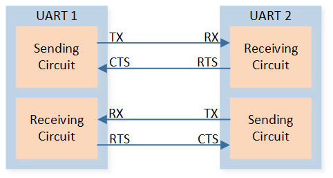
Schematic Diagram of Hardware Flow Control
RTS Flow Control
When the UART receiver is ready to accept new data, RTS becomes valid, and the low level is valid. When the number of data in the RX FIFO reaches the set RX trigger level, RTS becomes invalid (high level is invalid), thereby indicating that it is desired to stop data transmission at the end of the current frame.
CTS Flow Control
The transmitter checks the CTS before sending the next frame. If CTS is valid (low level is valid), the next data is sent; otherwise, the next frame data is not sent. If the CTS becomes invalid (high level is invalid) during transmission, the transmission is stopped after the current transmission is completed.
Baud Rate
Set the baud rate by configuring the variables div, ovsr, and ovsr_adj. UART baud rate table is shown below.
Baud Rate |
Variable div |
Variable ovsr |
Variable ovsr_adj |
|---|---|---|---|
1200 |
2589 |
7 |
0x7F7 |
9600 |
271 |
10 |
0x24A |
14400 |
271 |
5 |
0x222 |
19200 |
123 |
11 |
0x6FF |
28800 |
82 |
11 |
0x6FF |
38400 |
85 |
7 |
0x222 |
57600 |
41 |
11 |
0x6FF |
76800 |
35 |
9 |
0x7EF |
115200 |
20 |
12 |
0x252 |
128000 |
25 |
7 |
0x555 |
153600 |
15 |
12 |
0x252 |
230400 |
10 |
12 |
0x252 |
460800 |
5 |
12 |
0x252 |
500000 |
8 |
5 |
0 |
921600 |
3 |
9 |
0x2AA |
1000000 |
4 |
5 |
0 |
1382400 |
2 |
9 |
0x2AA |
1444400 |
2 |
8 |
0x5F7 |
1500000 |
2 |
8 |
0x492 |
1843200 |
2 |
5 |
0x3F7 |
2000000 |
2 |
5 |
0 |
2100000 |
2 |
14 |
0x400 |
2764800 |
1 |
9 |
0x2AA |
3000000 |
1 |
8 |
0x492 |
Program Examples
Initialization Flow
UART initialization flow is shown in the following figure.
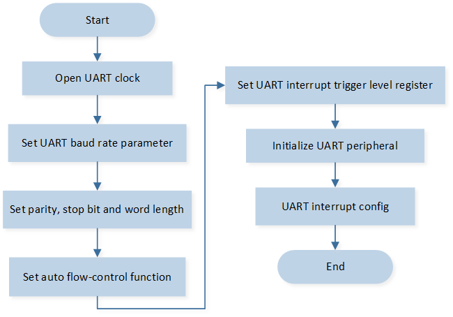
UART Initialization Flow Chart
The codes below demonstrate the UART interrupt handle flow.
/* Enable UART0 clock */
RCC_PeriphClockCmd(APBPeriph_UART0, APBPeriph_UART0_CLOCK, ENABLE);

UART_InitTypeDef uartInitStruct;
/* Fill each UART_InitTypeDef member variable with its default value */
UART_StructInit(&uartInitStruct);

/* Change default rx trigger level */
uartInitStruct.rxTriggerLevel = UART_RX_FIFO_TRIGGER_LEVEL_14BYTE;

UART_Init(UART0, &uartInitStruct);

//enable rx interrupt and line status interrupt
UART_INTConfig(UART0, UART_INT_RD_AVA | UART_INT_LINE_STS | UART_INT_IDLE, ENABLE);

RamVectorTableUpdate(UART0_VECTORn, (IRQ_Fun)Data_Uart_Handler);

NVIC_InitTypeDef NVIC_InitStruct;
NVIC_InitStruct.NVIC_IRQChannel = UART0_IRQn;
NVIC_InitStruct.NVIC_IRQChannelPriority = 3;
NVIC_InitStruct.NVIC_IRQChannelCmd = ENABLE;
NVIC_Init(&NVIC_InitStruct);
Receive Data by Interrupt Mode
UART interrupt handle flow is shown in the following figure.
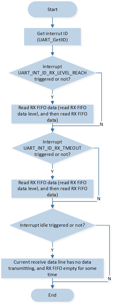
UART Interrupt Handle Flow
The codes below demonstrate the UART interrupt handle flow.
void data_uart_handler(void)
{
   uint8_t event = IO_DEMO_EVENT_UART_RX;
   uint32_t int_status = 0;
   uint8_t recv_len;
   uint8_t line_status = 0;

   if (UART_GetFlagState(UART0, UART_FLAG_RX_IDLE) == SET)
   {
      UART_INTConfig(UART0, UART_INT_IDLE, DISABLE);
      if (os_msg_send(io_queue_handle, &event, 0) == false)
      {
            IO_PRINT_ERROR0("data_uart_handler: Send Queue Error");
      }
      //user code here

      UART_INTConfig(UART0, UART_INT_IDLE, ENABLE);
   }

   /* read interrupt id */
   int_status = UART_GetIID(UART0);

   switch (int_status)
   {
   /* tx fifo empty, not enable */
   case UART_INT_ID_TX_EMPTY:
      break;

   /* rx data available */
   case UART_INT_ID_RX_LEVEL_REACH:
      recv_len = UART_GetRxFIFOLen(UART0);
      UART_ReceiveData(UART0, &RxBuffer[RxCount], recv_len);
      RxCount += recv_len;
      break;

   case UART_INT_ID_RX_TMEOUT:
      recv_len = UART_GetRxFIFOLen(UART0);
      UART_ReceiveData(UART0, &RxBuffer[RxCount], recv_len);
      RxCount += recv_len;

      break;

   /* receive line status interrupt */
   case UART_INT_ID_LINE_STATUS:
      line_status = UART_GetLineStatus(UART0);
      IO_PRINT_ERROR1("data_uart_handler: line_status 0x%x", line_status);
      UART_SendByte(UART0, line_status);
      break;

   default:
      break;
   }

   return;
}
Send Data
UART interrupt handle flow is shown in the following figure.
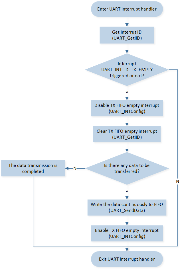
UART Interrupt Handle Flow
The codes below demonstrate the UART interrupt handle flow.
static void uart_send_data(uint8_t *buf, uint32_t len)
{
   uint32_t tx_len = len > UART_TX_FIFO_SIZE ? UART_TX_FIFO_SIZE : len;

   UART_SendData(UART0, buf, tx_len);

   uart_tx_curr_addr = buf + tx_len;
   uart_tx_len = len - tx_len;

   UART_INTConfig(UART0, UART_INT_FIFO_EMPTY, ENABLE);
}

static void uart0_interrupt_handler(void)
{
   uint32_t int_status = 0;

   /* read interrupt id */
   int_status = UART_GetIID(UART0);

   switch (int_status)
   {
   /* tx fifo empty */
   case UART_INT_ID_TX_EMPTY:
      UART_INTConfig(UART0, UART_INT_FIFO_EMPTY, DISABLE);
      UART_GetIID(UART0);
      if (uart_tx_len)
      {
            uart_send_data(uart_tx_curr_addr, uart_tx_len);
      }
      break;

   /* rx data available */
   case UART_INT_ID_RX_LEVEL_REACH:
      break;

   case UART_INT_ID_RX_TMEOUT:
      break;

   /* receive line status interrupt */
   case UART_INT_ID_LINE_STATUS:
      break;

   default:
      break;
   }
   return;
}