QDEC
QDEC Demo Code Support List
The description of QDEC demo code 1 is shown in the following table.
Demo 1 |
|
|---|---|
Sample Purpose |
Demonstrate how QDEC works. |
Brief Introduction |
This sample code demonstrates how QDEC works. The chip will detect the direction and count of wheel turns. |
File Path |
|
Function Entry |
|
Hardware Connection |
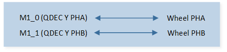
As shown in QDEC Demo Code 1 Hardware Connection Diagram. On EVB, connect P1_0 to the PHA of the wheel, connect P1_1 to the PHB of the wheel. |
QDEC PHA Pin Definition |
|
QDEC PHB Pin Definition |
|
QDEC Axial |
Y |
Scan Clock |
50KHz |
Debounce Clock |
5KHz |
Debounce |
Enable |
Debounce Time |
5ms |
Expected Result |
|
The hardware connection of QDEC demo code 1 is shown in the figure below.
QDEC Demo Code 1 Hardware Connection Diagram
Functional Overview
As shown in the following figure, QDEC is used to detect the motion state of the rotation-sensing device. When the rotating device moves, it will output two quadrature signals PHA and PHB. QDEC judges the direction of rotation by detecting the phase change of PHA and PHB.
Schematic Diagram of Two Quadrature Signals of QDEC
Feature List
Support 3 axes.
Support hardware debounce: debounce time for each axis can be set independently.
Support initial phase setting.
Support illegal phase change detection.
16-bit phase change counter.
Direction Judgment and Counting Method
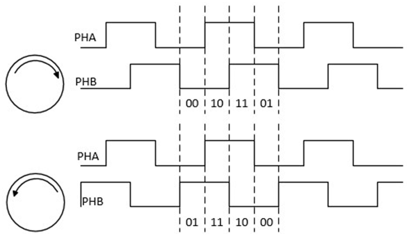
PHA and PHB are combined into a 2-bit number. PHA is the high bit, and PHB is the low bit.
The phases are divided into four types: 00, 01, 11, and 10.
As shown in the following figure, changes in the order of 00, 01, 11, and 10 are defined as positive. When the counter scale is set to 0, the counter will increase by one when the phase changes once. When the counter scale is set to 1, the counter will increase by one when the phase changes twice.
Changes in the order of 00, 10, 11, and 01 are defined as negative. When the counter scale is set to 0, the counter will decrease by one when the phase changes once. When the counter scale is set to 1, the counter will decrease by one when the phase changes twice.
PHA and PHB should only have one signal change at a time. If both signals change at the same time, the state is considered wrong. When this error state occurs, the counter does not count. Illegal interrupts can be turned on to detect this error condition.
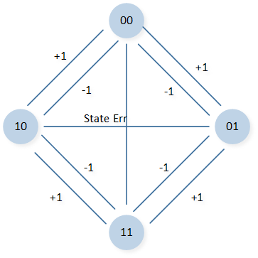
Schematic Diagram of QDEC Direction Judgment
Program Examples
Operation Flow
QDEC operation flow is shown in the following figure.
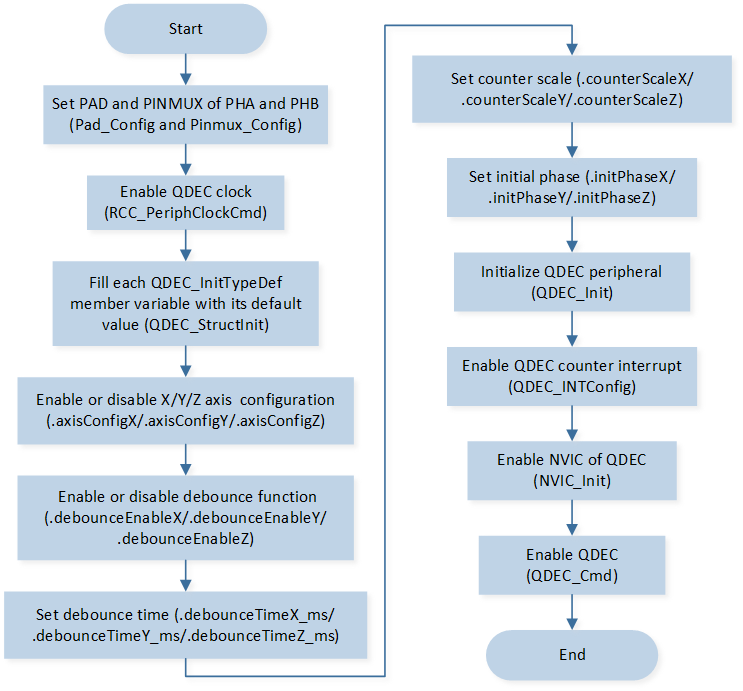
QDEC Operation Flow Chart
The codes below demonstrate the QDEC operation flow.
RCC_PeriphClockCmd(APBPeriph_QDEC, APBPeriph_QDEC_CLOCK, ENABLE);

QDEC_InitTypeDef qdecInitStruct;
QDEC_StructInit(&qdecInitStruct);
qdecInitStruct.ScanClockKHZ         = 50; /*!< 50KHz */
qdecInitStruct.DebonceClockKHZ     = 5; /*!< 5KHz */
qdecInitStruct.axisConfigY       = ENABLE;
qdecInitStruct.debounceEnableY   = Debounce_Enable;
qdecInitStruct.debounceTimeY     = 5 * 5; /*!< 5ms */

QDEC_Init(QDEC, &qdecInitStruct);

RamVectorTableUpdate(Qdecode_VECTORn, (IRQ_Fun)qdec_handler);
QDEC_INTConfig(QDEC, QDEC_Y_INT_NEW_DATA, ENABLE);

NVIC_InitTypeDef nvic_init_struct;
nvic_init_struct.NVIC_IRQChannel         = QDEC_IRQn;
nvic_init_struct.NVIC_IRQChannelCmd      = (FunctionalState)ENABLE;
nvic_init_struct.NVIC_IRQChannelPriority = 3;
NVIC_Init(&nvic_init_struct);

QDEC_Cmd(QDEC, QDEC_AXIS_Y, ENABLE);
QDEC interrupt handle flow is shown in the following figure.
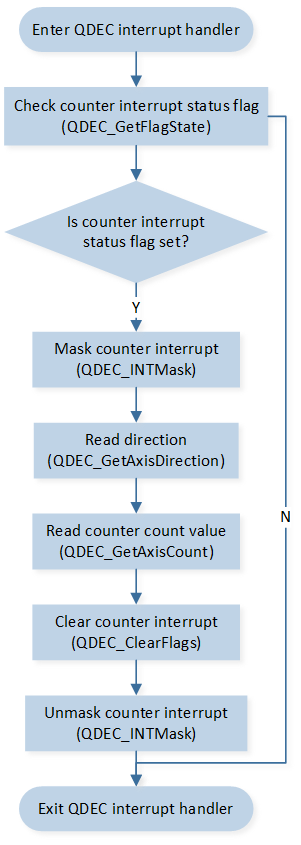
QDEC Interrupt Handle Flow Chart
The codes below demonstrate the QDEC interrupt handle flow.
void qdec_handler(void)
{
   /* Check Y-axis counter interrupt status flag */
   if (QDEC_GetFlagState(QDEC, QDEC_FLAG_NEW_CT_STATUS_Y) == SET)
   {
      /* Mask Y-axis counter interrupt */
      QDEC_INTMask(QDEC, QDEC_Y_CT_INT_MASK, ENABLE);

      /* Read direction */
      dir = QDEC_GetAxisDirection(QDEC, QDEC_AXIS_Y);
      /* Read counter count value */
      y_axis = QDEC_GetAxisCount(QDEC, QDEC_AXIS_Y);
      IO_PRINT_INFO2("qdec_handler: dir %d, y_axis %d", dir, y_axis);
      /* clear Y-axis counter interrupt status flag */
      QDEC_ClearFlags(QDEC, QDEC_CLR_NEW_CT_Y);
      /* Unmask Y-axis counter interrupt */
      QDEC_INTMask(QDEC, QDEC_Y_CT_INT_MASK, DISABLE);
   }
}