KeyScan
KeyScan Demo Code Support List
This chapter introduces the details of the KeyScan demo code.
KeyScan Demo in Active Mode
The description of KeyScan demo code 1 is shown in the following table.
Demo 1 |
|
|---|---|
Sample Purpose |
Demonstrates that KeyScan works in active mode. |
File Path |
|
Function Entry |
|
Hardware Connection |
As shown in KeyScan Demo Code Hardware Connection Diagram. EVB is connected to matrix keyboard module: connect M0_2 to ROW0, M0_3 to ROW1, M0_0 to COLUMN0, and M0_1 to COLUMN1. |
Pin Definition |
|
Expected Result |
|
The hardware connection of KeyScan demo code 1 is shown in the figure below.
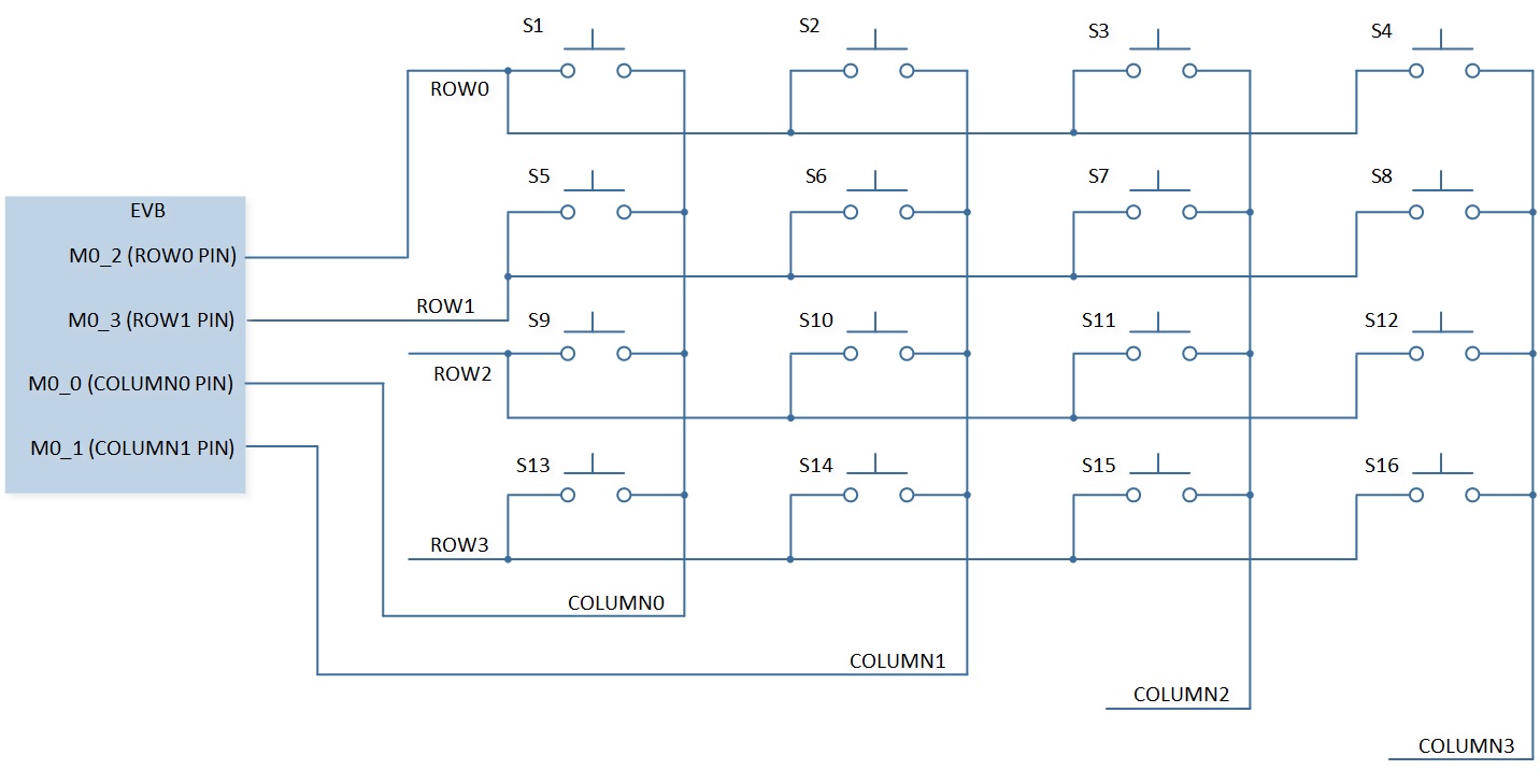
KeyScan Demo Code Hardware Connection Diagram
KeyScan Demo in DLPS Mode
The description of KeyScan demo code 2 is shown in the following table.
Demo 2 |
|
|---|---|
Sample Purpose |
Demonstrates that KeyScan works in DLPS mode. |
File Path |
|
Function Entry |
|
Hardware Connection |
As shown in KeyScan Demo Code Hardware Connection Diagram. EVB is connected to matrix keyboard module: connect M0_2 to ROW0, M0_3 to ROW1, M0_0 to COLUMN0, and M0_1 to COLUMN1. |
Pin Definition |
|
Expected Result |
|
Functional Overview
KeyScan needs to be used with an external key matrix. In the idle state, row[x] is input, pull high is required, column[y] is output low, and output mode must be open-drain. When any key is pressed, the level of the corresponding row changes from high to low, triggering KeyScan hardware scan action.
After the debounce is completed, the first scan starts. When scanning, the column[y] being scanned is output low, and the other columns output high. If row[x] is low at this time, it is considered that row[x] column[y] key is pressed.
Scan order is first column[0] fixed, scan from row[0] to row[x], then column[1] fixed, scan from row[0] to row[x], until column[y].
Feature List
Support 12 (row) * 20 (column) matrix scan.
Configurable number of rows (1-12), columns (1-20).
Support hardware debounce, configurable debounce time.
Configurable scan clock.
Support multi-key detection, up to 26 keys can be pressed at the same time.
Support periodic scan, configurable scan period.
26 bytes FIFO depth.
Support auto scan and manual scan.
Support all key release hardware detection.
Clock Divider
IO clock will be divided into 2 channels.
The KeyScan scan clock is generated by the frequency division of keyscan_clk_div (11 bits), which can be freely configured in the range of 10KHz ~ 100KHz.
The low-level delay clock is generated by the frequency division of keyscan_delay_div (6 bits) for use by the relevant timer.
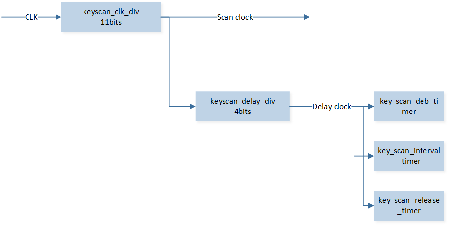
Schematic Diagram of KeyScan Clock Divider
Auto Scan Mode
The workflow of automatic scanning is shown in the figure below.
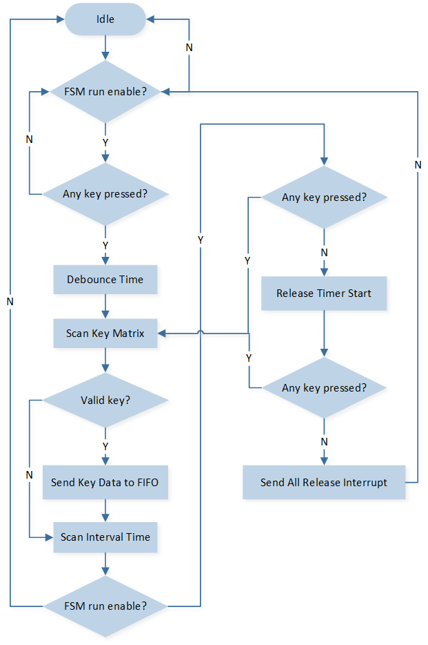
Auto Scan Flow Chart
Interrupt
KEYSCAN_INT_OVER_READWhen there is no data in the FIFO, reading the FIFO will trigger this interrupt to prevent over-reading.
KEYSCAN_INT_SCAN_ENDWhether the key value is scanned or not, the interrupt will be triggered as long as the scanning action is completed.
KEYSCAN_INT_FIFO_NOT_EMPTYIf there is data in the FIFO, the interrupt will be triggered.
KEYSCAN_INT_THRESHOLDThis interrupt is triggered when data in the FIFO reaches the threshold level.
KEYSCAN_INT_ALL_RELEASEWhen the release time count reaches the set value, if no key is pressed, the interrupt is triggered.
Program Examples
Operation Flow
KeyScan initialization flow is shown in the following figure.
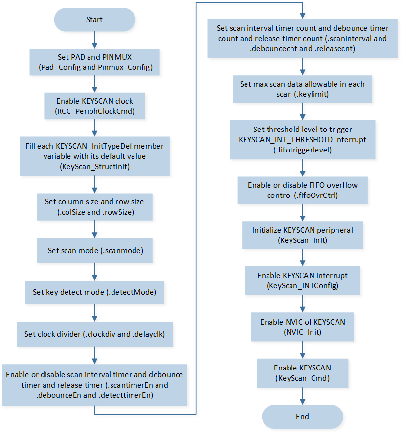
KeyScan Initialization Flow Chart
The codes below demonstrate the KeyScan initialization flow.
For details, please refer to src\sample\io_demo\keyscan\active\keyscan_demo.c.
RCC_PeriphClockCmd(APBPeriph_KEYSCAN, APBPeriph_KEYSCAN_CLOCK, ENABLE);
KEYSCAN_InitTypeDef  KeyScan_InitStruct;
KeyScan_StructInit(&KeyScan_InitStruct);
KeyScan_InitStruct.colSize         = KEYPAD_COLUMN_SIZE;
KeyScan_InitStruct.rowSize         = KEYPAD_ROW_SIZE;
KeyScan_InitStruct.scanInterval    = 0x80;
KeyScan_Init(KEYSCAN, &KeyScan_InitStruct);
KeyScan_INTConfig(KEYSCAN, KEYSCAN_INT_SCAN_END | KEYSCAN_INT_ALL_RELEASE, ENABLE);

NVIC_InitTypeDef nvic_init_struct;
nvic_init_struct.NVIC_IRQChannel         = KeyScan_IRQn;
nvic_init_struct.NVIC_IRQChannelCmd      = (FunctionalState)ENABLE;
nvic_init_struct.NVIC_IRQChannelPriority = 3;
NVIC_Init(&nvic_init_struct);

KeyScan_Cmd(KEYSCAN, ENABLE);