GPIO
GPIO Demo Code Support List
This chapter introduces the details of the GPIO demo code.
GPIO Demo for Input
The description of GPIO demo code 1 is shown in the following table.
Demo 1 |
|
|---|---|
Sample Purpose |
Demonstrates GPIO input mode. |
Brief Introduction |
This sample code demonstrates how to get the input level value of GPIO. |
File Path |
|
Function Entry |
|
GPIO Direction |
Input mode |
Pin Definition |
|
Expected Result |
Press the Reset button on the EVB, the string gpio_test: gpio_value 1 will be printed in Debug Analyzer. |
GPIO Demo for Output
The description of GPIO demo code 2 is shown in the following table.
Demo 2 |
|
|---|---|
Sample Purpose |
Demonstrates GPIO output mode. |
Brief Introduction |
This sample code demonstrates how to use GPIO to output high and low levels. |
File Path |
|
Function Entry |
|
GPIO Direction |
Output mode |
Hardware Connection |
As shown in GPIO Demo Code Hardware Connection Diagram. On EVB, connect P0_1 and LED1, and connect P0_2 and LED2. |
Pin Definition |
|
Expected Result |
Press the Reset button on the EVB. LED1 and LED2 will light up or off when the output level is selected as high or low. |
The hardware connection of GPIO demo code 2 is shown in the figure below.
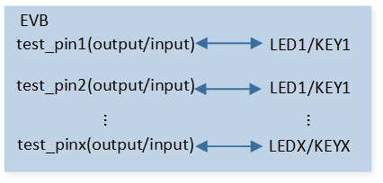
GPIO Demo Code Hardware Connection Diagram
GPIO Demo for Different Port (Single Pin Output)
The description of GPIO demo code 3 is shown in the following table.
Demo 3 |
|
|---|---|
Sample Purpose |
Demonstrates GPIOx output mode whether the pin belongs to GPIOA or B. |
Brief Introduction |
This sample code demonstrates the GPIOx output function. The output level value can be detected by connecting with LED. |
File Path |
|
Function Entry |
|
GPIO Direction |
Output mode |
Hardware Connection |
As shown in GPIO Demo Code Hardware Connection Diagram. On EVB, connect P4_3 and LED1. |
Pin Definition |
|
Expected Result |
Press the Reset button on the EVB. LED1 will light up or off when the gpio_pin_bit is selected to set or reset. |
GPIO Demo for Different Port (Multiple Pin Output)
The description of GPIO demo code 4 is shown in the following table.
Demo 4 |
|
|---|---|
Sample Purpose |
Demonstrates GPIOx group output mode whether the pins belong to GPIOA or B. |
Brief Introduction |
This sample code demonstrates the GPIOx group output function. These output level values can be detected by connecting with LED. |
File Path |
|
Function Entry |
|
GPIO Direction |
Output mode |
Hardware Connection |
As shown in GPIO Demo Code Hardware Connection Diagram. On EVB, connect LED and test pin. |
Expected Result |
Press the Reset button on the EVB. The LED will light up or off when the gpio_pin_bit is selected to set or reset. |
GPIO Demo for Interrupt Mode
The description of GPIO demo code 5 is shown in the following table.
Demo 5 |
|
|---|---|
Sample Purpose |
Demonstrates GPIO used as a key by edge trigger mode with hardware debounce. |
Brief Introduction |
This sample code demonstrates the detection of GPIO input through interrupt. When the button is pressed (such as P1_0 changing from high level to low level), the falling edge of GPIO is detected, and the GPIO interrupt is triggered. Then switch the edge trigger, after the button is released (P1_0 changes from low level to high level), the GPIO interrupt is triggered again. |
File Path |
|
Function Entry |
|
GPIO Direction |
Input mode |
Hardware Connection |
As shown in GPIO Demo Code Hardware Connection Diagram. On EVB, connect P1_0, P1_1, P2_1, P2_2 to KEY1 ~ KEY4 respectively. |
Pin Definition |
|
Expected Result |
Press the Reset button on the EVB. Press KEY1 ~ KEY4: gpio_isr_cb: pin_name P1_0, gpio_level 0 gpio_isr_cb: pin_name P1_1, gpio_level 1 gpio_isr_cb: pin_name P2_1, gpio_level 0 gpio_isr_cb: pin_name P2_2, gpio_level 1 will be printed in Debug Analyzer. Release KEY1 ~ KEY4: gpio_isr_cb: pin_name P1_0, gpio_level 1 gpio_isr_cb: pin_name P1_1, gpio_level 0 gpio_isr_cb: pin_name P2_1, gpio_level 1 gpio_isr_cb: pin_name P2_2, gpio_level 0 will be printed in Debug Analyzer. |
GPIO Demo for Key Detection by Level Trigger Mode
The description of GPIO demo code 6 is shown in the following table.
Demo 6 |
|
|---|---|
Sample Purpose |
Demonstrates GPIO used as a key by level trigger mode with TIMER debounce. |
Brief Introduction |
This sample code demonstrates the detection of GPIO input through interrupt. When the button is pressed (P0_0 changes from high level to low level), the low level of GPIO is detected, and the GPIO interrupt is triggered. Then restart the TIMER in the GPIO handler, after the 30ms debounce time, enter the TIMER handler to switch the level trigger, when the button is released (P1_0 changes from low level to high level), the GPIO interrupt is triggered again. Then the TIMER restarts again. |
File Path |
|
Function Entry |
|
GPIO Direction |
Input mode |
Hardware Connection |
As shown in GPIO Demo Code Hardware Connection Diagram. On EVB, connect P0_0 and KEY1. |
Pin Definition |
|
Expected Result |
Press the Reset button on the EVB. Press KEY1: key_handler: key_status 0 debounce_hw_timer_callback: Key press will be printed in Debug Analyzer. Release KEY1: key_handler: key_status 1 debounce_hw_timer_callback: Key release will be printed in Debug Analyzer. |
GPIO Demo for Key Detection by Edge Trigger Mode
The description of GPIO demo code 7 is shown in the following table.
Demo 7 |
|
|---|---|
Sample Purpose |
Demonstrates GPIO used as a key by edge trigger mode with hardware debounce. |
Brief Introduction |
This sample code demonstrates the detection of GPIO input through interrupt. When the button is pressed (P0_0 changes from high level to low level), the falling edge of GPIO is detected, and the GPIO interrupt is triggered. Then switch the edge trigger, after the button is released (P0_0 changes from low level to high level), the GPIO interrupt is triggered again. |
File Path |
|
Function Entry |
|
GPIO Direction |
Input mode |
Hardware Connection |
As shown in GPIO Demo Code Hardware Connection Diagram. On EVB, connect P0_0 and KEY1. |
Pin Definition |
|
Expected Result |
Press the Reset button on the EVB. Press KEY1: key_handler: Key press will be printed in Debug Analyzer. Release KEY1: key_handler: Key release will be printed in Debug Analyzer. |
GPIO Demo for GDMA Mode
The description of GPIO demo code 8 is shown in the following table.
Demo 8 |
|
|---|---|
Sample Purpose |
Demonstrates how GDMA controls GPIO output. |
Brief Introduction |
This sample code demonstrates how to use TIMER to toggle GDMA to control GPIO to output high and low levels of specified lengths. |
File Path |
|
GPIO Direction |
Output mode |
GDMA Direction |
Memory to Peripheral |
Function Entry |
|
Pin Definition |
|
Expected Result |
Press the Reset button on the EVB. Use a logic analyzer to capture the waveform of P0_2, and the output waveform results of single-block or multi-block are shown in GPIO Demo Code 8 Expected Result Diagram. |
The expected result of GPIO demo code 8 is shown in the figure below.
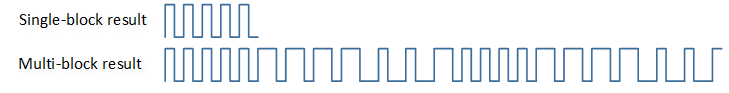
GPIO Demo Code 8 Expected Result Diagram
Functional Overview
The GPIO integrated core is programmable general-purpose input/output. Each GPIO pin can be configured by software as an output, input, or interrupt peripheral function.
Feature List
32 independently configured GPIO signals in every port, with independently controllable signal bits.
Support hardware and software control.
Support input and output control.
Support level-triggered and edge-triggered interrupts.
Support low and high level-triggered interrupts.
Support rising and falling edge-triggered interrupts.
Support both-edge-triggered interrupts.
Support hardware debounce function.
Support GPIO+TIMER+GDMA function.
Program Examples
Initialization Flow
The GPIO initialization flow is shown in the following figure.
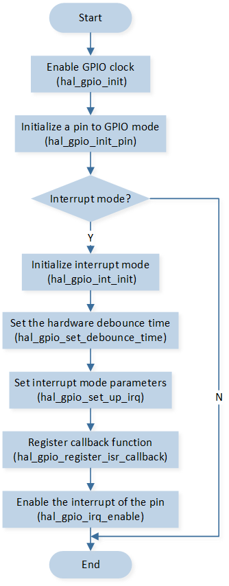
GPIO Initialization Flow Chart
Input Mode
The codes below demonstrate the operation flow of GPIO in input mode.
hal_gpio_init();
hal_gpio_init_pin(TEST_Pin, GPIO_TYPE_AUTO, GPIO_DIR_INPUT, GPIO_PULL_UP);
gpio_value = hal_gpio_get_input_level(TEST_Pin);
Output Mode
The codes below demonstrate the operation flow of GPIO in output mode.
hal_gpio_init();
hal_gpio_init_pin(TEST_PIN, GPIO_TYPE_CORE, GPIO_DIR_OUTPUT, GPIO_PULL_UP);
hal_gpio_init_pin(TEST_PIN_2, GPIO_TYPE_AON, GPIO_DIR_OUTPUT, GPIO_PULL_UP);

for (uint16_t i = 0; i < 10; i++)
{
   hal_gpio_set_level(TEST_PIN, GPIO_LEVEL_LOW);
   hal_gpio_set_level(TEST_PIN_2, GPIO_LEVEL_LOW);
   hal_gpio_set_level(TEST_PIN, GPIO_LEVEL_HIGH);
   hal_gpio_set_level(TEST_PIN_2, GPIO_LEVEL_HIGH);
}
Interrupt Mode
The codes below demonstrate the operation flow of GPIO in interrupt mode.
hal_gpio_init();
hal_gpio_int_init();
hal_gpio_set_debounce_time(30);

hal_gpio_init_pin(GPIO_DEMO_INPUT_PIN0, GPIO_TYPE_AUTO, GPIO_DIR_INPUT, GPIO_PULL_UP);
hal_gpio_init_pin(GPIO_DEMO_INPUT_PIN1, GPIO_TYPE_AUTO, GPIO_DIR_INPUT, GPIO_PULL_DOWN);
hal_gpio_init_pin(GPIO_DEMO_INPUT_PIN2, GPIO_TYPE_AUTO, GPIO_DIR_INPUT, GPIO_PULL_UP);
hal_gpio_init_pin(GPIO_DEMO_INPUT_PIN3, GPIO_TYPE_AUTO, GPIO_DIR_INPUT, GPIO_PULL_DOWN);

hal_gpio_set_up_irq(GPIO_DEMO_INPUT_PIN0, GPIO_IRQ_EDGE, GPIO_IRQ_ACTIVE_LOW, true);
hal_gpio_set_up_irq(GPIO_DEMO_INPUT_PIN1, GPIO_IRQ_EDGE, GPIO_IRQ_ACTIVE_HIGH, true);
hal_gpio_set_up_irq(GPIO_DEMO_INPUT_PIN2, GPIO_IRQ_EDGE, GPIO_IRQ_ACTIVE_LOW, true);
hal_gpio_set_up_irq(GPIO_DEMO_INPUT_PIN3, GPIO_IRQ_EDGE, GPIO_IRQ_ACTIVE_HIGH, true);

hal_gpio_register_isr_callback(GPIO_DEMO_INPUT_PIN0, gpio_isr_cb, GPIO_DEMO_INPUT_PIN0);
hal_gpio_register_isr_callback(GPIO_DEMO_INPUT_PIN1, gpio_isr_cb, GPIO_DEMO_INPUT_PIN1);
hal_gpio_register_isr_callback(GPIO_DEMO_INPUT_PIN2, gpio_isr_cb, GPIO_DEMO_INPUT_PIN2);
hal_gpio_register_isr_callback(GPIO_DEMO_INPUT_PIN3, gpio_isr_cb, GPIO_DEMO_INPUT_PIN3);

hal_gpio_irq_enable(GPIO_DEMO_INPUT_PIN0);
hal_gpio_irq_enable(GPIO_DEMO_INPUT_PIN1);
hal_gpio_irq_enable(GPIO_DEMO_INPUT_PIN2);
hal_gpio_irq_enable(GPIO_DEMO_INPUT_PIN3);