ADC
ADC Demo Code Support List
This chapter introduces the details of the ADC demo code.
ADC Demo for One Shot and Interrupt Mode
The description of ADC demo code 1 is shown in the following table.
Demo 1 |
|
|---|---|
Sample Purpose |
Demonstrates how ADC samples data by interrupt mode in one shot mode. |
Brief Introduction |
Uses one shot mode of ADC peripheral to measure voltage on P0_0, P0_1, VBAT, and VADP by interrupt. Prints voltage values in Debug Analyzer. |
File Path |
|
Function Entry |
|
Pre-Condition |
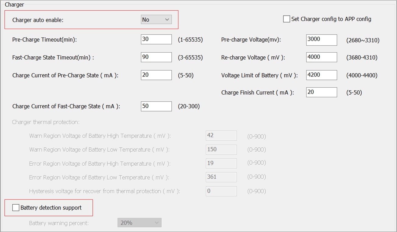
Turn off Charger auto enable and Battery detection support on the MCUConfig Tool. |
Channel |
ADC0 ADC1 VBAT VADPIN |
External Channel Input Mode |
ADC0 is divide mode and ADC1 is bypass mode. |
Hardware Connection |
|
Expected Result |
Prints voltage on P0_0, P0_1, VBAT and VADP in Debug Analyzer every 1000ms. |
The hardware connection of ADC demo code 1 is shown in the figure below.
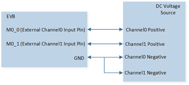
ADC Demo Code 1 Hardware Connection Diagram
ADC Demo for One Shot and Polling Mode
The description of ADC demo code 2 is shown in the following table.
Demo 2 |
|
|---|---|
Sample Purpose |
Demonstrates how ADC samples data by polling mode in one shot mode. |
Brief Introduction |
Uses one shot mode of ADC peripheral to measure voltage on P0_1, VBAT, and VADP by polling. Prints voltage values in Debug Analyzer. |
File Path |
|
Function Entry |
|
Pre-Condition |
Turn off Charger auto enable and Battery detection support on the MCUConfig Tool. |
Channel |
ADC1 VBAT VADPIN |
External Channel Input Mode |
ADC1 is divide mode. |
Hardware Connection |
|
Expected Result |
Prints voltage on P0_1, VBAT, and VADP in Debug Analyzer. |
ADC Demo for Hardware Average Mode
The description of ADC demo code 3 is shown in the following table.
Demo 3 |
|
|---|---|
Sample Purpose |
Demonstrates how ADC samples data with hardware average function. |
Brief Introduction |
Uses the hardware average function of the ADC peripheral to measure voltage on P0_1 and prints voltage values in Debug Analyzer. |
File Path |
|
Function Entry |
|
Pre-Condition |
Turn off Charger auto enable and Battery detection support on the MCUConfig Tool. |
Channel |
ADC1 |
External Channel Input Mode |
ADC1 is divide mode. |
Hardware Connection |
Connect M0_1 of EVB to an external DC voltage source. Input voltage of M0_1 must range from 0 to 3.3V. |
Expected Result |
Print voltage on P0_1 in Debug Analyzer. |
ADC Demo for ADC Manager Mode
The description of ADC demo code 4 is shown in the following table.
Demo 4 |
|
|---|---|
Sample Purpose |
Demonstrate how ADC samples data by ADC manager. |
Brief Introduction |
Uses one shot mode of the ADC peripheral to measure voltage on VBAT and VADP by ADC manager. Prints sample raw data in Debug Analyzer. |
File Path |
|
Function Entry |
|
Channel |
VBAT VADPIN |
Hardware Connection |
|
Expected Result |
Print sample raw data in Debug Analyzer. |
ADC Demo for Continuous Mode
The description of ADC demo code 5 is shown in the following table.
Demo 5 |
|
|---|---|
Sample Purpose |
Demonstrates how ADC samples data in continuous mode with charger and discharger enabled. |
Brief Introduction |
Uses continuous mode of the ADC peripheral to measure voltage on P0_0 with charger and discharger enabled. Prints sample raw data and voltage in Debug Analyzer. |
File Path |
|
Function Entry |
|
Pre-Condition |
Turn on Charger auto enable and Battery detection support on the MCUConfig Tool. |
Channel |
ADC0 |
External Channel Input Mode |
ADC0 is divide mode. |
Hardware Connection |
Connect M0_0 of EVB to an external DC voltage source. Input voltage of M0_0 must range from 0 to 3.3V. |
Expected Result |
When VADP and U_5V_FT are connected, ADC stops continuous sampling. When VADP and U_5V_FT are disconnected, ADC starts continuous sampling and prints sample raw data and voltage on P0_0 in Debug Analyzer. |
ADC Demo for VBAT and NTC Detection
The description of ADC demo code 6 is shown in the following table.
Demo 6 |
|
|---|---|
Sample Purpose |
Demonstrates how ADC samples NTC and VBAT voltage. |
Brief Introduction |
Uses one shot mode of the ADC peripheral to measure voltage on VBAT and NTC by ADC manager. Prints voltage values in Debug Analyzer. |
File Path |
|
Function Entry |
|
Channel |
ADC0 ADC1 VBAT |
External Channel Input Mode |
ADC0 and ADC1 are bypass mode. |
Hardware Connection |
|
Expected Result |
Prints voltage on VBAT and NTC in Debug Analyzer every 500ms. |
Functional Overview
Feature List
VBAT and VADPIN internal channels.
Two external channel input modes: bypass mode and divide mode.
Support single-ended mode.
Two work modes: one shot mode and continuous mode.
16 index schedule table.
TIMER 7 triggers ADC one shot mode sampling.
32 depth FIFO for continuous mode.
Support hardware average function.
Pin
RTL87x3D supports 8 external channels: external channel 0, 1, 2, 3, 4, 5, 6, and 7 correspond to pin P0_0, P0_1, P0_2, P0_3, P0_4, P0_5, P0_6, and P0_7.
RTL87x3E and RTL87x3EP support 4 external channels: external channel 0, 1, 2, and 3 correspond to pin P0_0, P0_1, P0_2, and P0_3.
Channel Mode
Single-Ended Mode
Single-Ended mode occupies one channel and uses only one pin for sampling.
Internal VBAT and Internal VADPIN Modes
Internal VBAT mode is used to measure VBAT voltage. Internal VADPIN mode is used to measure VADP voltage.
External Channel Input Mode
Bypass Mode
The input range of ADC bypass mode is 0 to 0.9V.
Divide Mode
The input range of ADC divide mode is 0 to 3.3V.
Work Mode
One Shot Mode
After ADC is enabled, only one sampling is performed. To sample again, the user needs to manually restart sampling.
It can cooperate with TIMER 7 peripheral to realize timing continuous sampling.
Continuous Mode
After ADC is enabled, sampling continues until ADC is disabled.
It can cooperate with GDMA continuous sampling.
Schedule Table Index
ADC has 16 schedule tables. Write the parameters in the table below into schIndex[0] ~ schIndex[15] to set channel mode and channel number.
Then set bitmap, schIndex[0] ~ schIndex[15] corresponding to bit 0 ~ bit 15 of bitmap. If the specific bit of bitmap is set to 1, it means that the schedule table corresponding to this bit is enabled. For example, if config schIndex[0] and schIndex[1], then bitmap is
0000 0000 0011(that is,0x0003), if config schIndex[0] and schIndex[2], then bitmap is0000 0000 0101(that is,0x0005).After ADC is enabled, ADC will sample successively according to the mode configured in the enabled schedule table.
|
Description |
|---|---|
|
Single-Ended mode, the input is external channel 0. |
|
Single-Ended mode, the input is external channel 1. |
|
Single-Ended mode, the input is external channel 2. |
|
Single-Ended mode, the input is external channel 3. |
|
Single-Ended mode, the input is external channel 4. |
|
Single-Ended mode, the input is external channel 5. |
|
Single-Ended mode, the input is external channel 6. |
|
Single-Ended mode, the input is external channel 7. |
|
Internal battery voltage detection channel. |
|
Internal adapter voltage detection channel. |
Program Examples
One Shot Mode Operation Flow
Polling Mode
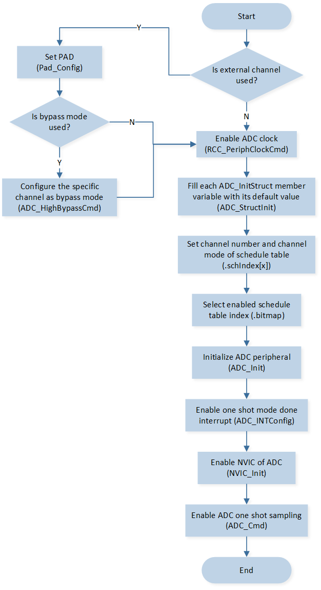
The flow of ADC sampling in one shot mode by polling is shown in the following figure.
ADC One Shot Sampling by Polling Mode
The codes below demonstrate the flow of ADC sampling in one shot mode by polling. For details, please refer to src\sample\io_demo\adc\one-shot\adc_polling_demo.c.
Note
To use the method below, please turn off Charger auto enable and Battery detection support on the MCUConfig Tool. As shown in Turn Off Charger on the MCUConfig Tool.
/* Enable ADC clock */
RCC_PeriphClockCmd(APBPeriph_ADC, APBPeriph_ADC_CLOCK, ENABLE);

ADC_InitTypeDef adc_init_struct;
/* Fill each ADC_InitStruct member variable with its default value */
ADC_StructInit(&adc_init_struct);

/* Write the parameters into schedule table to set channel mode and channel number. */
adc_init_struct.schIndex[0] = EXT_SINGLE_ENDED(1);
adc_init_struct.schIndex[1] = INTERNAL_VBAT_MODE;
adc_init_struct.schIndex[2] = INTERNAL_VADPIN_MODE;
/* Set bitmap, schIndex[0] ~ schIndex[15] corresponding to bit0 ~ bit15 of bitmap.
   If the specific bit of bitmap is set to 1, it means that the schedule table corresponding to this bit is enabled.
   For example, if config schIndex[0] and schIndex[1], then bitmap is 0000 0000 0011 (that is, 0x0003),
   if config schIndex[0] and schIndex[2], then bitmap is 0000 0000 0101 (that is, 0x0005).
   After ADC is enabled, ADC will sample successively according to the mode configured in the enabled schedule table.
   */
adc_init_struct.bitmap = 0x07;
/* Initialize ADC */
ADC_Init(ADC, &adc_init_struct);

/* Enable ADC one shot mode done interrupt */
ADC_INTConfig(ADC, ADC_INT_ONE_SHOT_DONE, ENABLE);

/* Disable NVIC of ADC */
NVIC_InitTypeDef NVIC_InitStruct;
NVIC_InitStruct.NVIC_IRQChannel = ADC_IRQn;
NVIC_InitStruct.NVIC_IRQChannelPriority = 3;
NVIC_InitStruct.NVIC_IRQChannelCmd = DISABLE;
NVIC_Init(&NVIC_InitStruct);

/* Enable ADC one shot sampling.
   When ADC is enabled, sampling will be done quickly.
   After initialization, ADC can be enabled when sampling is needed. */
ADC_Cmd(ADC, ADC_One_Shot_Mode, ENABLE);

/* Check ADC_INT_ONE_SHOT_DONE interrupt status flag */
while (ADC_GetIntFlagStatus(ADC, ADC_INT_ONE_SHOT_DONE) == RESET);

/* Clear ADC_INT_ONE_SHOT_DONE interrupt */
ADC_ClearINTPendingBit(ADC, ADC_INT_ONE_SHOT_DONE);

/* ADC one shot sampling mode, read data from schedule table.
   The schedule table index which config in ADC init function.
   The value is 0 ~ 15 */
data[0] = ADC_Read(ADC, 0);
data[1] = ADC_Read(ADC, 1);
data[2] = ADC_Read(ADC, 2);

/* Get conversion results based on data. The unit of the result is mV. */
res[0] = ADC_GetRes(data[0], EXT_SINGLE_ENDED(1));
res[1] = ADC_GetRes(data[1], INTERNAL_VBAT_MODE);
res[2] = ADC_GetRes(data[2], INTERNAL_VADPIN_MODE);
Turn Off Charger on the MCUConfig Tool
Interrupt Mode
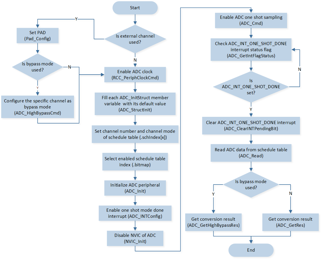
The flow of ADC sampling in one shot mode by interrupt is shown in the following figure.
ADC One Shot Sampling by Interrupt Mode
The codes below demonstrate the flow of ADC sampling in one shot mode by interrupt. For details, please refer to src\sample\io_demo\adc\one-shot\adc_demo.c.
Note
To use the method below, please turn off Charger auto enable and Battery detection support on the MCUConfig Tool.
/* Bypass mode config, please notice that the input voltage of
   ADC channel using bypass mode should not be over 0.9V */
ADC_HighBypassCmd(1, ENABLE);

/* Enable ADC clock */
RCC_PeriphClockCmd(APBPeriph_ADC, APBPeriph_ADC_CLOCK, ENABLE);

ADC_InitTypeDef adcInitStruct;
/* Fill each ADC_InitStruct member variable with its default value */
ADC_StructInit(&adcInitStruct);

/* Write the parameters into schedule table to set channel mode and channel number. */
adcInitStruct.schIndex[0] = EXT_SINGLE_ENDED(0);
adcInitStruct.schIndex[1] = EXT_SINGLE_ENDED(1);
adcInitStruct.schIndex[2] = INTERNAL_VBAT_MODE;
adcInitStruct.schIndex[3] = INTERNAL_VADPIN_MODE;
/* Set bitmap, schIndex[0] ~ schIndex[15] corresponding to bit0 ~ bit15 of bitmap.
   If the specific bit of bitmap is set to 1, it means that the schedule table corresponding to this bit is enabled.
   For example, if config schIndex[0] and schIndex[1], then bitmap is 0000 0000 0011 (that is, 0x0003).
   If config schIndex[0] and schIndex[2], then bitmap is 0000 0000 0101 (that is, 0x0005).
   After ADC is enabled, ADC will sample successively according to the mode configured in the enabled schedule table.
   */
adcInitStruct.bitmap = 0x0f;
/* Initialize ADC */
ADC_Init(ADC, &adcInitStruct);

/* Enable ADC one shot mode done interrupt */
ADC_INTConfig(ADC, ADC_INT_ONE_SHOT_DONE, ENABLE);

/* Enable NVIC of ADC */
NVIC_InitTypeDef NVIC_InitStruct;
NVIC_InitStruct.NVIC_IRQChannel = ADC_IRQn;
NVIC_InitStruct.NVIC_IRQChannelPriority = 2;
NVIC_InitStruct.NVIC_IRQChannelCmd = ENABLE;
NVIC_Init(&NVIC_InitStruct);

/* Enable ADC one shot sampling.
   When ADC is enabled, sampling will be done quickly and interruption will occur.
   After initialization, ADC can be enabled when sampling is needed. */
ADC_Cmd(ADC, ADC_One_Shot_Mode, ENABLE);
ADC interrupt handle flow is shown in the following figure.
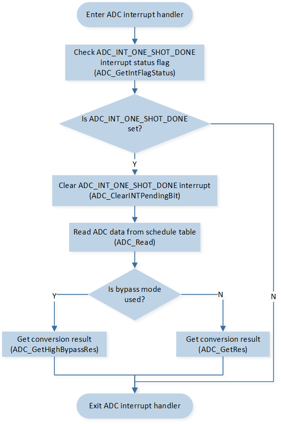
ADC Interrupt Handle Flow
The codes below demonstrate the ADC interrupt handle flow.
void adc_handler(void)
{
   int32_t data[4];
   int32_t res[4];

   /* Check ADC_INT_ONE_SHOT_DONE interrupt status flag */
   if (ADC_GetIntFlagStatus(ADC, ADC_INT_ONE_SHOT_DONE) == SET)
   {
      /* Clear ADC_INT_ONE_SHOT_DONE interrupt */
      ADC_ClearINTPendingBit(ADC, ADC_INT_ONE_SHOT_DONE);
      /* ADC one shot sampling mode, read data from schedule table.
         The schedule table index which config in ADC_Init function.
         The value is 0 ~ 15 */
      data[0] = ADC_Read(ADC, 0);
      data[1] = ADC_Read(ADC, 1);
      data[2] = ADC_Read(ADC, 2);
      data[3] = ADC_Read(ADC, 3);
      /* Get conversion results based on data. The unit of the result is mV. */
      res[0] = ADC_GetRes(data[0], EXT_SINGLE_ENDED(0));
      res[1] = ADC_GetHighBypassRes(data[1], EXT_SINGLE_ENDED(1));
      res[2] = ADC_GetRes(data[2], INTERNAL_VBAT_MODE);
      res[3] = ADC_GetRes(data[3], INTERNAL_VADPIN_MODE);
   }
}
Hardware Average Mode
ADC hardware average function can only be used in one shot mode and only schedule table 0 can be used. For RTL87x3E and RTL87x3EP, it is recommended to use the hardware average function. The flow of ADC sampling in one shot mode by hardware average is shown in the following figure.

ADC One Shot Sampling by Hardware Average Mode
The codes below demonstrate the flow of ADC sampling in one shot mode by hardware average. For details, please refer to
src\sample\io_demo\adc\adc_hw_average\adc_hw_average_demo.c.
Note
To use the method below, please turn off Charger auto enable and Battery detection support on the MCUConfig Tool.
/* Enable ADC clock */
RCC_PeriphClockCmd(APBPeriph_ADC, APBPeriph_ADC_CLOCK, ENABLE);

ADC_InitTypeDef adc_init_struct;
/* Fill each ADC_InitStruct member variable with its default value */
ADC_StructInit(&adc_init_struct);

/* When hardware average function is enabled, ADC can only use schedule table 0 */
adc_init_struct.schIndex[0] = EXT_SINGLE_ENDED(1);
adc_init_struct.bitmap = 0x01;
/* Initialize ADC */
ADC_Init(ADC, &adc_init_struct);

/* Enable ADC hardware average function */
ADC_HwEvgEn(ADC, ENABLE);
/* Set the hardware average number of times */
ADC_HwEvgSel(ADC, ADC_DTAT_AVG_SEL_BY32);

/* Enable ADC one shot mode done interrupt */
ADC_INTConfig(ADC, ADC_INT_ONE_SHOT_DONE, ENABLE);

/* Enable NVIC of ADC */
NVIC_InitTypeDef NVIC_InitStruct;
NVIC_InitStruct.NVIC_IRQChannel = ADC_IRQn;
NVIC_InitStruct.NVIC_IRQChannelPriority = 3;
NVIC_InitStruct.NVIC_IRQChannelCmd = ENABLE;
NVIC_Init(&NVIC_InitStruct);

/* Enable ADC one shot sampling.
   When ADC is enabled, sampling will be done quickly and interruption will occur.
   After initialization, ADC can be enabled when sampling is needed. */
ADC_Cmd(ADC, ADC_One_Shot_Mode, ENABLE);
ADC interrupt handle flow is shown in the following figure.
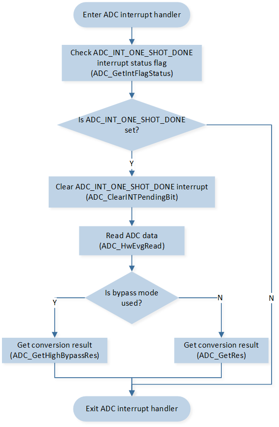
ADC Interrupt Handle Flow
The codes below demonstrate the ADC interrupt handle flow.
void adc_handler(void)
{
   int32_t data;
   int32_t result;

   /* Check ADC_INT_ONE_SHOT_DONE interrupt status flag */
   if (ADC_GetIntFlagStatus(ADC, ADC_INT_ONE_SHOT_DONE) == SET)
   {
      /* Clear ADC_INT_ONE_SHOT_DONE interrupt */
      ADC_ClearINTPendingBit(ADC, ADC_INT_ONE_SHOT_DONE);
      /* Read ADC data */
      data = ADC_HwEvgRead(ADC);
      /* Get conversion results based on data. The unit of the result is mV. */
      result = ADC_GetRes(data, EXT_SINGLE_ENDED(1));
   }
}
ADC Manager Mode
When the internal charger is enabled, it is necessary to use ADC manager mode for ADC sampling. The flow of ADC sampling in one shot mode by ADC manager is shown in the following figure.

ADC One Shot Sampling by ADC Manager Mode
The codes below demonstrate the flow of ADC sampling in one shot mode by ADC manager. For details, please refer to
src\sample\io_demo\adc\adc_charger_demo\adc_charger_demo.c and src\sample\io_demo\adc\adc_manger\adc_manager_demo.c.
Note
To use the method below, please turn on Charger auto enable and Battery detection support on the MCUConfig Tool.
/* Bypass mode config, please notice that the input voltage of
   ADC channel using bypass mode should not be over 0.9V */
ADC_HighBypassCmd(0, ENABLE);
ADC_HighBypassCmd(1, ENABLE);

ADC_InitTypeDef ADC_InitStruct;
/* Fill each ADC_InitStruct member variable with its default value */
ADC_StructInit(&ADC_InitStruct);

/* Set bitmap, schIndex[0] ~ schIndex[15] corresponding to bit0 ~ bit15 of bitmap.
   If the specific bit of bitmap is set to 1, it means that the schedule table corresponding to this bit is enabled.
   For example, if config schIndex[0] and schIndex[1], then bitmap is 0000 0000 0011 (that is, 0x0003),
   if config schIndex[0] and schIndex[2], then bitmap is 0000 0000 0101 (that is, 0x0005).
   After ADC is enabled, ADC will sample successively according to the mode configured in the enabled schedule table.
   */
ADC_InitStruct.bitmap = 0x0007;
/* Write the parameters into schedule table to set channel mode and channel number. */
ADC_InitStruct.schIndex[0] = EXT_SINGLE_ENDED(0);
ADC_InitStruct.schIndex[1] = EXT_SINGLE_ENDED(1);
ADC_InitStruct.schIndex[2] = INTERNAL_VBAT_MODE;

/* Request for a channel in ADC manager */
if (!adc_mgr_register_req(&ADC_InitStruct,
                              (adc_callback_function_t)app_adc_vbat_ntc_voltage_read_callback,
                              &adc_channel_vbat_ntc_voltage))
{
   IO_PRINT_ERROR0("app_adc_vbat_ntc_voltage_init: adc_mgr_register_req failed");
}

/* Enable the specific ADC manager channel for sampling */
adc_mgr_enable_req(adc_channel_vbat_ntc_voltage);
ADC manager callback handle flow is shown in the following figure.
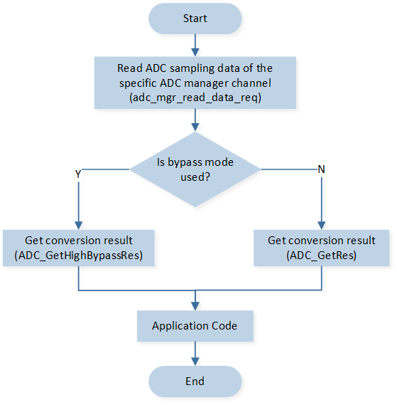
ADC Manager Callback Handle Flow
The codes below demonstrate the ADC manager callback handle flow.
static void app_adc_vbat_ntc_voltage_read_callback(void *pvPara, uint32_t int_status)
{
   uint16_t adc_data[3];
   uint16_t sched_bit_map = 0x0007;

   /* Read ADC sampling data of the specific ADC manager channel */
   adc_mgr_read_data_req(adc_channel_vbat_ntc_voltage, adc_data, sched_bit_map);

   /* Get conversion results based on data. The unit of the result is mV. */
   adc_charger_data_mgr.temperature_battery_1 = ADC_GetHighBypassRes(adc_data[0], EXT_SINGLE_ENDED(0));
   adc_charger_data_mgr.temperature_battery_2 = ADC_GetHighBypassRes(adc_data[1], EXT_SINGLE_ENDED(1));
   adc_charger_data_mgr.voltage_battery = ADC_GetRes(adc_data[2], INTERNAL_VBAT_MODE);
}
Continuous Mode Operation Flow
GDMA Mode
The flow of ADC sampling in continuous mode by GDMA is shown in the following figure.
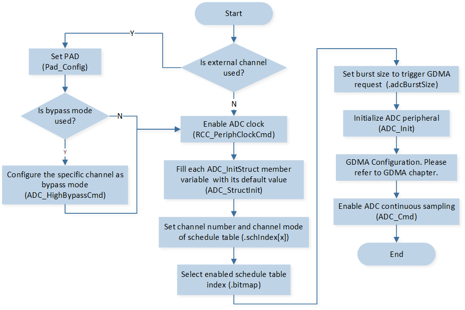
ADC Continuous Sampling by GDMA Mode
The codes below demonstrate the flow of ADC sampling in continuous mode by GDMA. For details, please refer to src\sample\io_demo\gdma\adc_dma\adc_gdma_demo.c.
Note
To use the method below, please turn off Charger auto enable and Battery detection support on the MCUConfig Tool.
Please refer to
src\sample\io_demo\adc\adc_continuous_mode\adc_continuous_mode_demo.cfor use of the internal charger and ADC continuous sampling mode at the same time.
/* Enable ADC clock */
RCC_PeriphClockCmd(APBPeriph_ADC, APBPeriph_ADC_CLOCK, ENABLE);

ADC_InitTypeDef adc_init_struct;
/* Fill each ADC_InitStruct member variable with its default value */
ADC_StructInit(&adc_init_struct);

/* Write the parameters into schedule table to set channel mode and channel number. */
adc_init_struct.schIndex[0] = EXT_SINGLE_ENDED(0);
/* Set bitmap, schIndex[0] ~ schIndex[15] corresponding to bit0 ~ bit15 of bitmap.
   If the specific bit of bitmap is set to 1, it means that the schedule table corresponding to this bit is enabled.
   For example, if config schIndex[0] and schIndex[1], then bitmap is 0000 0000 0011 (that is, 0x0003),
   if config schIndex[0] and schIndex[2], then bitmap is 0000 0000 0101 (that is, 0x0005).
   After ADC is enabled, ADC will sample successively according to the mode configured in the enabled schedule table.
   */
adc_init_struct.bitmap = 0x01;
/* Set burst size to trigger GDMA request */
adc_init_struct.adcBurstSize = 8;
/* Initialize ADC */
ADC_Init(ADC, &adc_init_struct);