SLEEP LED
SLEEP LED Demo Code Support List
This chapter introduces the details of the SLEEP LED demo code.
SLEEP LED Demo for Breathe Mode
The description of SLEEP LED demo code 1 is shown in the following table.
Demo 1 |
|
|---|---|
Sample Purpose |
Demonstrate SLEEP LED breathe mode. |
File Path |
|
Function Entry |
|
Phase0 Parameters |
Duty update time: 10ms Phase0 output time: 500ms Initial high level time: 0 Duty step time: 0.03125ms Change direction: increase |
Phase1 Parameters |
Duty update time: 10ms Phase1 output time: 500ms Initial high level time: 3.125ms Duty step time: 0.0625ms Change direction: increase |
Phase2 Parameters |
Duty update time: 10ms Phase2 output time: 500ms Initial high level time: 6.25ms Duty step time: 0.09375ms Change direction: increase |
Phase3 Parameters |
Duty update time: 10ms Phase3 output time: 500ms Initial high level time: 9.375ms Duty step time: 0.125ms Change direction: increase |
Phase4 Parameters |
Duty update time: 10ms Phase4 output time: 500ms Initial high level time: 9.375ms Duty step time: 0.03125ms Change direction: decrease |
Phase5 Parameters |
Duty update time: 10ms Phase5 output time: 500ms Initial high level time: 6.25ms Duty step time: 0.0625ms Change direction: decrease |
Phase6 Parameters |
Duty update time: 10ms Phase6 output time: 500ms Initial high level time: 3.125ms Duty step time: 0.09375ms Change direction: decrease |
Phase7 Parameters |
Duty update time: 10ms Phase7 output time: 500ms Initial high level time: 0 Duty step time: 0 Change direction: decrease |
Hardware Connection |
As shown in SLEEP LED Demo Code Hardware Connection Diagram. On EVB, connect M0_1 to LED1 and connect M2_1 to LED2 and connect M2_2 to LED3. |
Pin Definition |
|
Expected Result |
LEDs turn from dark to bright and then from bright to dark in breathe mode. |
The hardware connection of SLEEP LED demo code 1 is shown in the figure below.
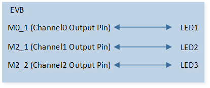
SLEEP LED Demo Code Hardware Connection Diagram
SLEEP LED Demo for Blink Mode
The description of SLEEP LED demo code 2 is shown in the following table.
Demo 2 |
|
|---|---|
Sample Purpose |
Demonstrate SLEEP LED blink mode. |
File Path |
|
Function Entry |
|
Period Parameters |
Channel0: period0, period1, and period2 high level time is 200ms, period0, period1, and period2 low level time is 100ms. Channel1: period0 and period1 high level time is 200ms, period0 and period1 low level time is 100ms, period2 high level and low level time are 0. Channel2: period0 high level time is 200ms, period0 low level time is 100ms, period1 and period2 high level and low level time are 0. |
Hardware Connection |
As shown in SLEEP LED Demo Code Hardware Connection Diagram. On EVB, connect M0_1 to LED1 and connect M2_1 to LED2 and connect M2_2 to LED3. |
Pin Definition |
|
Expected Result |
LEDs blink with 200ms on and 100ms off. |
Functional Overview
SLEEP LED is used to control LED to make the effect of blinking light or breathing light.
Feature List
Support three channels.
Support blink mode and breathe mode.
32KHz clock source.
3 periods per channel in blink mode.
8 phases per channel in breathe mode.
Support output level setting in idle state.
Support reverse output function.
Support period bypass in blink mode and phase bypass in breathe mode.
Note
If a default pull-up pin (P1_0/P1_1/P2_0/P3_0/P3_1) is set as a high active LED, or any other pull-down pin is set as a low active LED, it will blink when CPU reboots.
Blink Mode
In blink mode, one channel is divided into three periods. As shown in the following figure, it is executed sequentially from period0, and after the end of period2, it goes back to period0 to continue the loop execution.
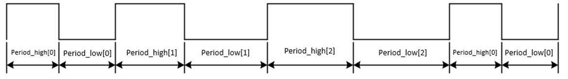
Schematic Diagram of SLEEP LED Blink Mode
Note
period_timetick = prescale / 32000
periodx high level time = period_high[x] * period_timetick (x = 0, 1, 2)
periodx low level time = period_low[x] * period_timetick (x = 0, 1, 2)
If period_high[x] or period_low[x] is 0, this and subsequent periods are bypassed. For example, if period_high[2] is 0, period2 is bypassed, it is executed sequentially from period0, and after the end of period1, it goes to period0 to continue the loop execution.
Breathe Mode
In breathe mode, one channel is divided into eight phases. As shown in the following figure, it is executed sequentially from phase0, and after the end of phase7, it goes to phase0 to continue the loop execution.
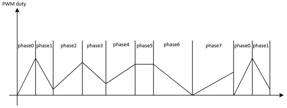
Schematic Diagram of SLEEP LED Breathe Mode
Note
phase_timetick = prescale / 32000
phase_uptate_rate[x]: duty update time = (phase_uptate_rate[x] + 1) * phase_timetick (x = 0, 1, 2, …, 7)
phase_phase_tick[x]: The duration of the whole phase. phasex output time = phase_phase_tick[x] * phase_timetick (x = 0, 1, 2, …, 7)
phase_initial_duty[x]: initial high level time = phase_initial_duty[x] / 32000 (x = 0, 1, 2, …, 7)
phase_increase_duty[x]: The direction of each change of duty. 1: increase duty. 0: decrease duty. (x = 0, 1, 2, …, 7)
phase_duty_step[x]: duty step time = phase_duty_step[x] / 32000 (x = 0, 1, 2, …, 7)
After high level time increases to phase_timetick, it remains at phase_timetick.
After high level time decreases to 0, it remains at 0.
Low level time = phase_timetick - high level time
If phase_phase_tick[x] is 0, this and subsequent phases are bypassed. For example, if phase_phase_tick[6] is 0, phase6 and phase7 are bypassed, it is executed sequentially from phase0, and after the end of phase5, it goes to phase0 to continue the loop execution.
Idle State
Call the SleepLed_SetIdleMode() API to set whether the channel outputs a high level or low level after the SLEEP LED is disabled.
Reverse Output Function
Each channel of SLEEP LED supports the reverse function. After the reverse function is enabled, the original waveform is reversed and output, the actual waveform is opposite to the set value.
Program Examples
Blink Mode Operation Flow
The operation flow of SLEEP LED blink mode is shown in the following figure.
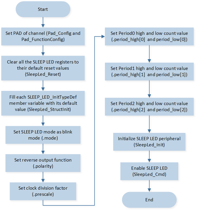
SLEEP LED Blink Mode Flow Chart
The codes below demonstrate the SLEEP LED blink mode operation flow.
/* Clear all the SLEEP LED registers to their default reset values */
SleepLed_Reset();

SLEEP_LED_InitTypeDef Led_Initsturcture;
/* Fill each SLEEP_LED_InitTypeDef member variable with its default value */
SleepLed_StructInit(&Led_Initsturcture);

/* Set SLEEP LED mode */
Led_Initsturcture.mode                        = LED_BLINK_MODE;
/* Set reverse output function */
Led_Initsturcture.polarity                    = LED_OUTPUT_NORMAL;
/* Set clock division factor */
Led_Initsturcture.prescale                    = 32;
/* Set period0 high and low count value */
Led_Initsturcture.period_high[0]              = 200;
Led_Initsturcture.period_low[0]               = 100;
/* Set period1 high and low count value */
Led_Initsturcture.period_high[1]              = 200;
Led_Initsturcture.period_low[1]               = 100;
/* Set period2 high and low count value */
Led_Initsturcture.period_high[2]              = 200;
Led_Initsturcture.period_low[2]               = 100;
/* Initialize channel 0 */
SleepLed_Init(LED_CHANNEL_0, &Led_Initsturcture);

Led_Initsturcture.period_high[2]              = 0;
Led_Initsturcture.period_low[2]               = 0;
/* Initialize channel 1 */
SleepLed_Init(LED_CHANNEL_1, &Led_Initsturcture);

Led_Initsturcture.period_high[1]              = 0;
Led_Initsturcture.period_low[1]               = 0;
/* Initialize channel 2 */
SleepLed_Init(LED_CHANNEL_2, &Led_Initsturcture);
/* Enable Sleep led */
SleepLed_Cmd(LED_CHANNEL_1 | LED_CHANNEL_0 | LED_CHANNEL_2, ENABLE);
Breathe Mode Operation Flow
The operation flow of SLEEP LED breathe mode is shown in the following figure.
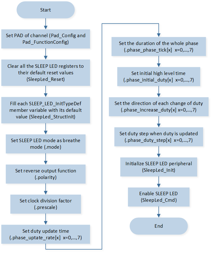
SLEEP LED Breathe Mode Flow Chart
The codes below demonstrate the SLEEP LED breathe mode operation flow.
/* Clear all the Sleep LED registers to their default reset values */
SleepLed_Reset();

SLEEP_LED_InitTypeDef Led_Initsturcture;
/* Fill each SLEEP_LED_InitTypeDef member variable with its default value */
SleepLed_StructInit(&Led_Initsturcture);

/* Set clock division factor */
Led_Initsturcture.prescale                    = 320;
/* Set SLEEP LED mode */
Led_Initsturcture.mode                        = LED_BREATHE_MODE;
/* Set reverse output function */
Led_Initsturcture.polarity                    = LED_OUTPUT_NORMAL;
/* Set duty update time */
Led_Initsturcture.phase_uptate_rate[0]              = 0;
/* Set the duration of the whole phase */
Led_Initsturcture.phase_phase_tick[0]               = 50;
/* Set initial high level time */
Led_Initsturcture.phase_initial_duty[0]             = 0;
/* Set the direction of each change of duty */
Led_Initsturcture.phase_increase_duty[0]            = 1;
/* Set duty step when duty is updated */
Led_Initsturcture.phase_duty_step[0]                = 1;

/* Set phase1 parameters */
Led_Initsturcture.phase_uptate_rate[1]              = 0;
Led_Initsturcture.phase_phase_tick[1]               = 50;
Led_Initsturcture.phase_initial_duty[1]             = 100;
Led_Initsturcture.phase_increase_duty[1]            = 1;
Led_Initsturcture.phase_duty_step[1]                = 2;

/* Set phase2 parameters */
Led_Initsturcture.phase_uptate_rate[2]              = 0;
Led_Initsturcture.phase_phase_tick[2]               = 50;
Led_Initsturcture.phase_initial_duty[2]             = 200;
Led_Initsturcture.phase_increase_duty[2]            = 1;
Led_Initsturcture.phase_duty_step[2]                = 3;

/* Set phase3 parameters */
Led_Initsturcture.phase_uptate_rate[3]              = 0;
Led_Initsturcture.phase_phase_tick[3]               = 50;
Led_Initsturcture.phase_initial_duty[3]             = 300;
Led_Initsturcture.phase_increase_duty[3]            = 1;
Led_Initsturcture.phase_duty_step[3]                = 4;

/* Set phase4 parameters */
Led_Initsturcture.phase_uptate_rate[4]              = 0;
Led_Initsturcture.phase_phase_tick[4]               = 50;
Led_Initsturcture.phase_initial_duty[4]             = 300;
Led_Initsturcture.phase_increase_duty[4]            = 0;
Led_Initsturcture.phase_duty_step[4]                = 1;

/* Set phase5 parameters */
Led_Initsturcture.phase_uptate_rate[5]              = 0;
Led_Initsturcture.phase_phase_tick[5]               = 50;
Led_Initsturcture.phase_initial_duty[5]             = 200;
Led_Initsturcture.phase_increase_duty[5]            = 0;
Led_Initsturcture.phase_duty_step[5]                = 2;

/* Set phase6 parameters */
Led_Initsturcture.phase_uptate_rate[6]              = 0;
Led_Initsturcture.phase_phase_tick[6]               = 50;
Led_Initsturcture.phase_initial_duty[6]             = 100;
Led_Initsturcture.phase_increase_duty[6]            = 0;
Led_Initsturcture.phase_duty_step[6]                = 3;

/* Set phase7 parameters */
Led_Initsturcture.phase_uptate_rate[7]              = 0;
Led_Initsturcture.phase_phase_tick[7]               = 50;
Led_Initsturcture.phase_initial_duty[7]             = 0;
Led_Initsturcture.phase_increase_duty[7]            = 0;
Led_Initsturcture.phase_duty_step[7]                = 0;
/* Initialize channel 0 */
SleepLed_Init(LED_CHANNEL_0, &Led_Initsturcture);
/* Initialize channel 1 */
SleepLed_Init(LED_CHANNEL_1, &Led_Initsturcture);
/* Initialize channel 2 */
SleepLed_Init(LED_CHANNEL_2, &Led_Initsturcture);
/* Enable Sleep led */
SleepLed_Cmd(LED_CHANNEL_1 | LED_CHANNEL_0 | LED_CHANNEL_2, ENABLE);