TIMER and PWM
TIMER and PWM Demo Code Support List
This chapter introduces the details of the TIMER and PWM demo code.
TIMER Demo for Reload Mode
The description of TIMER and PWM demo code 1 is shown in the following table.
Demo 1 |
|
|---|---|
Sample Purpose |
Demonstrates how TIMER module works in reload mode and it will trigger the interrupt every 3 seconds. |
File Path |
|
Function Entry |
|
Timeout |
3 seconds |
Expected Result |
Print string demo_hw_timer_callback in Debug Analyzer every 3 seconds. |
PWM Demo for Normal and Complementary Output
The description of TIMER and PWM demo code 2 is shown in the following table.
Demo 2 |
|
|---|---|
Sample Purpose |
Demonstrates PWM output, PWM complementary output, and deadzone. |
File Path |
|
Function Entry |
|
Pin Definition |
|
Hardware Connection |
Connect M0_0 of EVB to channel 0 of the logic analyzer, connect M0_2 of EVB to channel 1 of the logic analyzer, and connect M0_3 of EVB to channel 2 of the logic analyzer. |
Expected Result |
The waveforms displayed by channels 0/1/2 of the logic analyzer are shown in TIMER and PWM Demo Code 2 Expected Result Diagram. |
The expected result of TIMER and PWM demo code 2 is shown in the figure below.
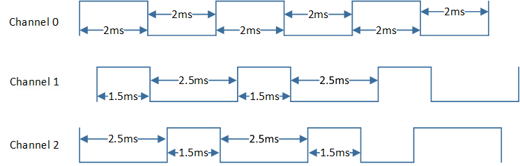
TIMER and PWM Demo Code 2 Expected Result Diagram
PWM Demo for Breath and Blink LED
The description of TIMER and PWM demo code 3 is shown in the following table.
Demo 3 |
|
|---|---|
Sample Purpose |
Demonstrates how to achieve the effect of breath and blink LED with PWM. |
File Path |
|
Function Entry |
|
Pin Definition |
|
Hardware Connection |
On EVB, connect M2_1 to LED0, connect M2_2 to LED1, and connect M2_7 to LED2. |
Expected Result |
LEDs turn from dark to bright and then from bright to dark with the effect of breath light. |
Functional Overview
The TIMER consists of a 32-bit automatic load counter. Each TIMER is completely independent and does not share any resources. They can operate synchronously together. The TIMER can operate in two modes: user-defined count mode and free-running mode. In user-defined count mode, the TIMER counts down from the value set by the user. In free-running mode, the TIMER counts down from 0xffffffff. When the TIMER counter is enabled after being reset or disabled, the TIMER counts down from its initial value, and when it reaches 0, an interrupt is triggered.
Feature List
Two operation modes: user-defined count mode and free-running mode.
TIMER counter width: 32 bits.
Support PWM output mode.
TIMER 2 and TIMER 3 support PWM complementary output mode.
TIMER 2 and TIMER 3 support deadzone.
TIMER 2 and TIMER 3 support emergency stop control.
Note
RTL87x3D supports up to 16 TIMER, 12 of which can be used for application.
RTL87x3E supports up to 8 TIMER, 5 of which can be used for application.
RTL87x3EP supports up to 12 TIMER, 9 of which can be used for application, but only 5 of which can be used for the PWM function.
TIMER 0 and TIMER 1 are reserved for low stack. TIMER 7 is reserved for log time stamp.
Program Examples
TIMER Operation Flow
The codes below demonstrate the TIMER operation flow. For details, please refer to src\sample\io_demo\tim\interrupt\tim_demo.c.
void tim_driver_init(void)
{
   /* Create the timer, user-defined mode, the period is 3 seconds. */
   demo_timer_handle = hw_timer_create("demo_hw_timer", 3000 * 1000, true, demo_hw_timer_callback);
   if (demo_timer_handle == NULL)
   {
      IO_PRINT_ERROR0("tim_driver_init: fail to create hw timer, check hw timer usage");
      return;
   }

   IO_PRINT_TRACE1("tim_driver_init: create hw timer instance successfully, id %d",
                  hw_timer_get_id(demo_timer_handle));

   /* Start the specified timer */
   hw_timer_start(demo_timer_handle);
}
When the TIMER counter reaches to zero, the interrupt will be triggered and the callback will be executed. The codes below demonstrate the TIMER callback handle flow.
void demo_hw_timer_callback(T_HW_TIMER_HANDLE handle)
{
   //Add User code here
   IO_PRINT_TRACE0("demo_hw_timer_callback");
}
PWM Operation Flow
The codes below demonstrate the PWM operation flow. For details, please refer to src\sample\io_demo\tim\pwm\pwm_demo.c.
static void driver_pwm_init(void)
{
   T_PWM_CONFIG demo_pwm_deadzone_para;

   /* Create the PWM, high-level time is 2 seconds, low-level time is 2 seconds */
   demo_pwm_handle = pwm_create("demo_pwm", PWM_HIGH_LEVEL_CNT, PWM_LOW_LEVEL_CNT, false);
   if (demo_pwm_handle == NULL)
   {
      IO_PRINT_ERROR0("driver_pwm_init: Fail to create pwm handle");
      return;
   }

   /* Configure PIN ADC_0 as PWM output */
   pwm_pin_config(demo_pwm_handle, PWM_OUT_PIN, PWM_FUNC);
   /* Start the specified PWM */
   pwm_start(demo_pwm_handle);

   /* Create the PWM, deadzone is enabled. */
   demo_pwm_deadzone_handle = pwm_create("demo_pwm_deadzone", PWM_HIGH_LEVEL_CNT, PWM_LOW_LEVEL_CNT,
                                          true);
   if (demo_pwm_deadzone_handle == NULL)
   {
      IO_PRINT_ERROR0("driver_pwm_init: Fail to create pwm deadzone handle");
      return;
   }

   /* Set high-level time */
   demo_pwm_deadzone_para.pwm_high_count = PWM_HIGH_LEVEL_CNT;
   /* Set low-level time */
   demo_pwm_deadzone_para.pwm_low_count = PWM_LOW_LEVEL_CNT;
   /* Enable deadzone */
   demo_pwm_deadzone_para.pwm_deadzone_enable = ENABLE;
   /* Configure PWM clock source as 1MHz */
   demo_pwm_deadzone_para.clock_source = PWM_CLOCK_1M;
   /* Set deadzone size count, count frequency is 32K */
   demo_pwm_deadzone_para.pwm_deadzone_size = PWM_DEADZONE_SIZE_CNT;
   /* Configure PWM_P emergency stop state as low-level */
   demo_pwm_deadzone_para.pwm_p_stop_state = PWM_DEAD_ZONE_STOP_LOW;
   /* Configure PWM_N emergency stop state as high-level */
   demo_pwm_deadzone_para.pwm_n_stop_state = PWM_DEAD_ZONE_STOP_HIGH;
   /* Initialize PWM */
   pwm_config(demo_pwm_deadzone_handle, &demo_pwm_deadzone_para);

   /* Configure PIN ADC_2 as PWM_P output */
   pwm_pin_config(demo_pwm_deadzone_handle, PWM_OUT_PIN_P, PWM_FUNC_P);
   /* Configure PIN ADC_3 as PWM_N output */
   pwm_pin_config(demo_pwm_deadzone_handle, PWM_OUT_PIN_N, PWM_FUNC_N);
   /* Start the specified PWM */
   pwm_start(demo_pwm_deadzone_handle);
}