PINMUX and PAD
PAD Demo Code Support List
This chapter introduces the details of the PAD demo code.
PAD Demo for Wake Up Function
The description of PAD demo code 1 is shown in the following table.
Demo 1 |
|
|---|---|
Sample Purpose |
Demonstrates how PAD wakes up the system from DLPS mode. |
Brief Introduction |
This sample code demonstrates how PAD wakes up the system.
|
File Path |
|
Function Entry |
|
Pin Definition |
|
Hardware Connection |
When the system needs to be woken up, connect M0_0 to GND on EVB. |
Expected Result |
|
PAD Demo for Interrupt Mode
The description of PAD demo code 2 is shown in the following table.
Demo 2 |
|
|---|---|
Sample Purpose |
Demonstrates PAD interrupt mode to realize key detection. |
Brief Introduction |
This sample code demonstrates key detection by PAD interrupt mode. When the button is pressed (such as P1_0 changing from high level to low level), the low level of the pin is detected, and the system handler is triggered. Then switch the level trigger, after the button is released (P1_0 changes from low level to high level), the system handler is triggered again. |
File Path |
|
Function Entry |
|
GPIO Direction |
Input Mode |
Hardware Connection |
On EVB, connect P1_0, P1_1, P2_1, P2_2 to KEY1 ~ KEY4 respectively. |
Pin Definition |
|
Expected Result |
Press the Reset button on the EVB. Press KEY1: system_handler: pin0 interrupt triggered, pin_0_state 0 will be printed in Debug Analyzer. Release KEY1: system_handler: pin0 interrupt triggered, pin_0_state 1 will be printed in Debug Analyzer. |
Functional Overview
PINMUX is an abbreviation for pin multiplexing. Because the SoC has a limited number of pins, pin multiplexing allows the SoC to use the limited pins for various functions, such as SPI, I2C, and GPIO.
PAD is used to control the behavior of a pin, such as pull-up or pull-down, output high or low level, and wake-up functions.
As shown in the figure below. The PINMUX circuit and IO modules are in the core domain and will be powered down during low power mode, so they cannot work during low power mode. The PAD circuit is in the AON domain and will not be powered down during low power mode, so the PAD can work normally during low power mode. The PAD is mainly used to maintain the pin output state or wake up the system in low power mode.
The PAD can be configured as PINMUX mode and software mode. Only when the PAD is set to PINMUX mode, can this pin be connected to the core domain to achieve pin multiplexing.
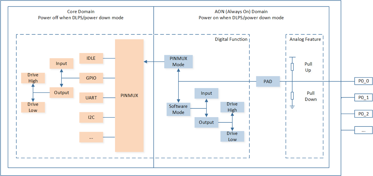
Schematic Diagram of PINMUX and PAD Circuit
Feature List
Two operating modes: PINMUX mode and software mode.
Configurable pin pull-up or pull-down resistors.
Configurable pin independently output high or low level in software mode.
Keep power during DLPS/power down mode, powered off in ship mode.
Wake up the system from DLPS and power down mode from high or low triggers on all the pins.
Hybrid PAD Usage
The hybrid PAD can be configured in digital mode or analog mode. Configure the mode of the hybrid PAD by calling Pad_AnalogMode() function.
/* Configure MIC1_P as analog mode */
Pad_AnalogMode(MIC1_P, PAD_ANALOG_MODE);
When the hybrid PAD is configured in digital mode (GPIO, I2C, etc), the AVCCDRV always on option needs to be configured as Always active on the MCUConfig Tool.
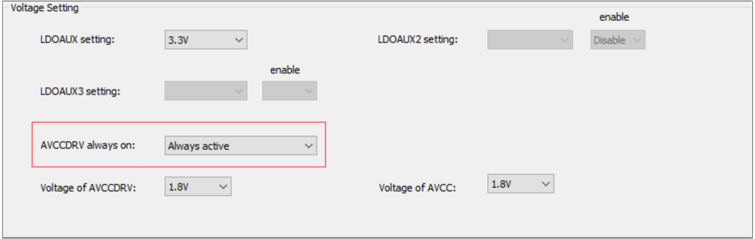
Set AVCCDRV Always On Option
Note
RTL87x3D hybrid PAD:
LOUT_N,P_UART,ROUT_N,ROUT_P,MIC1_N,MIC1_P,MIC2_N,MIC2_P,MIC3_N,MIC3_P,MIC4_N,MIC4_P,MIC5_N,MIC5_P,MIC6_N,MIC6_P,AUX_R,AUX_L,MICBIAS.RTL87x3E hybrid PAD:
AUX_R,AUX_L,MIC1_P,MIC1_N,MIC2_P,MIC2_N,MICBIAS,LOUT_P,LOUT_N,ROUT_P,ROUT_N,MIC3_P,MIC3_N.RTL87x3EP hybrid PAD:
DAOUT_P,DAOUT_N,MIC1_P,MIC1_N,MIC2_P,MIC2_N,MICBIAS.