CAN
This document introduces the configuration and usage of CAN. CAN is a communication protocol used in vehicles and industrial automation systems. It is designed to address communication issues between electronic control units within a vehicle. With advantages such as efficiency, reliability, and strong real-time capabilities, the CAN protocol has been widely applied in various embedded systems. The document includes an introduction to CAN demo code, an overview of CAN functionalities, and a description of the configuration flow.
CAN Demo Code Support List
This chapter introduces the details of the CAN demo code.
CAN Demo for Loopback Mode
The description of CAN demo code 1 is shown in the following table.
Demo 1 |
|
|---|---|
Sample Purpose |
Demonstrates the CAN works in loopback mode. |
Brief Introduction |
This sample code demonstrates the CAN works in loopback mode. CAN sends messages to itself and receives them. |
File Path |
|
Function Entry |
|
CAN ID |
CAN0 |
CAN Speed |
500000 |
Expected Result |
|
CAN Demo for TX and RX
The description of CAN demo code 2 is shown in the following table.
Demo 2 |
|
|---|---|
Sample Purpose |
Demonstrates how CAN sends and receives data. |
Brief Introduction |
This sample code demonstrates the CAN communicates with the PC through a USB CAN analyzer. The CAN sends data to the PC, receives data sent by the PC in the CAN interrupt, and transmits the same data back to the PC. The PC then receives the data sent by the chip. |
File Path |
|
Function Entry |
|
Hardware Connection |
As shown in CAN Demo Code Hardware Connection Diagram. On EVB, connect P4_0 to the CTX of the CAN receiver. On EVB, connect P4_1 to the CRX of the CAN receiver. On EVB, connect BAT/5V to the VCC of the CAN receiver. On EVB, connect GND to the GND of the CAN receiver. Connect the CANH of the CAN receiver to the CANH of the USB CAN. Connect the CANL of the CAN receiver to the CANL of the USB CAN. |
CAN TX PIN |
|
CAN RX PIN |
|
CAN ID |
CAN0 |
CAN Speed |
500000 |
Expected Result |
|
The hardware connection of CAN demo code 2 is shown in the figure below.

CAN Demo Code Hardware Connection Diagram
The schematic diagram of CAN USB tool is shown below.
CAN USB Tool
CAN Demo for GDMA Mode
The description of CAN demo code 3 is shown in the following table.
Demo 3 |
|
|---|---|
Sample Purpose |
Demonstrates how CAN sends and receives data in GDMA mode. |
Brief Introduction |
This sample code demonstrates the CAN communicates with the PC through a USB CAN analyzer. The CAN sends data to the PC, receives data sent by the PC in the CAN interrupt, and transmits the same data back to the PC. The PC then receives the data sent by the chip. |
File Path |
|
Function Entry |
|
Hardware Connection |
As shown in CAN Demo Code Hardware Connection Diagram. On EVB, connect P4_0 to the CTX of the CAN receiver. On EVB, connect P4_1 to the CRX of the CAN receiver. On EVB, connect BAT/5V to the VCC of the CAN receiver. On EVB, connect GND to the GND of the CAN receiver. Connect the CANH of the CAN receiver to the CANH of the USB CAN. Connect the CANL of the CAN receiver to the CANL of the USB CAN. |
CAN TX PIN |
|
CAN RX PIN |
|
CAN ID |
CAN0 |
CAN Speed |
500000 |
Expected Result |
|
CAN Demo for Auto Reply Mode
The description of CAN demo code 4 is shown in the following table.
Demo 4 |
|
|---|---|
Sample Purpose |
Demonstrates how CAN sends and receives data in auto reply mode. |
Brief Introduction |
This sample code demonstrates the CAN communicates with the PC through a USB CAN analyzer. When the CAN receives a remote frame, it automatically replies with a message. When the CAN transmits a remote frame, it automatically receives a message. |
File Path |
|
Function Entry |
|
Hardware Connection |
As shown in CAN Demo Code Hardware Connection Diagram. On EVB, connect P4_0 to the CTX of the CAN receiver. On EVB, connect P4_1 to the CRX of the CAN receiver. On EVB, connect BAT/5V to the VCC of the CAN receiver. On EVB, connect GND to the GND of the CAN receiver. Connect the CANH of the CAN receiver to the CANH of the USB CAN. Connect the CANL of the CAN receiver to the CANL of the USB CAN. |
CAN TX PIN |
|
CAN RX PIN |
|
CAN ID |
CAN0 |
CAN Speed |
500000 |
Expected Result |
|
CAN Demo in DLPS Mode
The description of CAN demo code 5 is shown in the following table.
Demo 5 |
|
|---|---|
Sample Purpose |
Demonstrates how CAN sends and receives data when DLPS is enabled. |
Brief Introduction |
This sample code demonstrates the CAN communicates with the PC through a USB CAN analyzer when DLPS is enabled. When entering DLPS, the CAN will automatically save its settings, and upon exiting DLPS, it will automatically restore these settings. To prevent leakage, the user needs to configure the PAD according to the actual circuit when entering and exiting DLPS. |
File Path |
|
Function Entry |
|
Hardware Connection |
As shown in CAN Demo Code Hardware Connection Diagram. On EVB, connect P4_0 to the CTX of the CAN receiver. On EVB, connect P4_1 to the CRX of the CAN receiver. On EVB, connect BAT/5V to the VCC of the CAN receiver. On EVB, connect GND to the GND of the CAN receiver. Connect the CANH of the CAN receiver to the CANH of the USB CAN. Connect the CANL of the CAN receiver to the CANL of the USB CAN. |
CAN TX PIN |
|
CAN RX PIN |
|
CAN ID |
CAN0 |
CAN Speed |
500000 |
Expected Result |
|
CAN Demo for GDMA Mode with DLPS Enabled
The description of CAN demo code 6 is shown in the following table.
Demo 6 |
|
|---|---|
Sample Purpose |
Demonstrates how CAN sends and receives data in GDMA mode when DLPS is enabled. |
Brief Introduction |
This sample code demonstrates the CAN communicates with the PC through a USB CAN analyzer when DLPS is enabled. When entering DLPS, the CAN will automatically save its settings, and upon exiting DLPS, it will automatically restore these settings. To prevent leakage, the user needs to configure the PAD according to the actual circuit when entering and exiting DLPS. Additionally, the user needs to restore the GDMA when exiting DLPS. |
File Path |
|
Function Entry |
|
Hardware Connection |
As shown in CAN Demo Code Hardware Connection Diagram. On EVB, connect P4_0 to the CTX of the CAN receiver. On EVB, connect P4_1 to the CRX of the CAN receiver. On EVB, connect BAT/5V to the VCC of the CAN receiver. On EVB, connect GND to the GND of the CAN receiver. Connect the CANH of the CAN receiver to the CANH of the USB CAN. Connect the CANL of the CAN receiver to the CANL of the USB CAN. |
CAN TX PIN |
|
CAN RX PIN |
|
CAN ID |
CAN0 |
CAN Speed |
500000 |
Expected Result |
|
Functional Overview
CAN module is targeted for CAN bus communication according to ISO11898-1-2015 standard and CAN 2.0 A/B. The module also has a part of memory logic for flexible transmission and reception of CAN messages. The logic eases the loading of the CPU and increases efficiency.
Note
Only RTL87x3EP supports CAN.
CAN in RTK belongs to the controller part of the CAN bus system structure. When communicating with other CAN devices, an external CAN receiver is also required.
Feature List
Full implementation of CAN 2.0 A/B.
Multiple interrupts.
Time stamp support.
Message RAM to store RX/TX packet for easing the loading of CPU.
Loop back mode and silence mode support.
Part of RAM configure as FIFO.
GDMA function for TX and RX.
Auto reply for remote message.
Auto re-transmission.
Warning function when error counter larger than threshold (default 96).
Timer triggered message in TX.
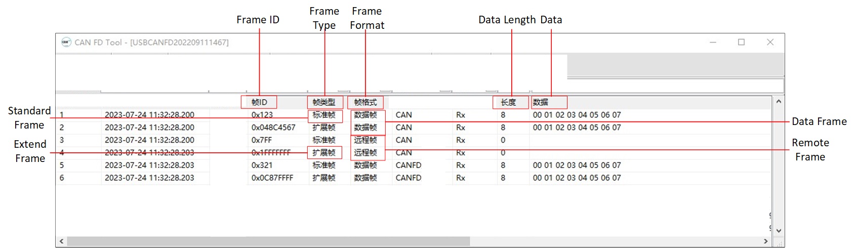
Support Frame Type
We support Standard Data Frame, Extended Data Frame, Standard Remote Frame, and Extended Remote Frame. These frames are CAN frames from ISO11898, and detailed explanations can be found in the ISO standards.
Bit Timing
The CAN clock is derived by dividing the system clock, and one cycle is referred to as tq, representing the smallest time unit for the operation of the CAN controller.
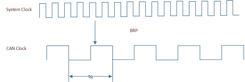
CAN Clock
During initialization, the CAN clock can be determined by adjusting the following parameter:
void can_driver_init(void)
{
   /* Standard CAN Bit Timing BRP  = can_brp + 1 */
   init_struct.CAN_BitTiming.b.can_brp = 3;
}
The effective BRP is the set value plus 1.
CAN does not have a clock line, so it uses bit synchronization to ensure the timing of communication and to correctly sample the bus levels. The CAN bit timing is as follows:
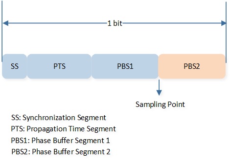
CAN Bit Timing
SS
The units on the bus perform timing adjustments through this segment.
The length is fixed at 1 tq.
PTS
A segment used to absorb physical delays on the network. The unit is tq.
PBS1
A segment used for compensation when adjusting timing. The unit is tq.
PBS2
A segment used for compensation when adjusting timing. The unit is tq.
SJW
Resynchronization jump width, the maximum value for compensation. The unit is tq.
During the initialization process, the bit timing can be obtained by setting the following parameters:
void can_driver_init(void)
{
   /* Initialize CAN. */
   CAN_InitTypeDef init_struct = {0};
   CAN_StructInit(&init_struct);
   init_struct.CAN_AutoReTxEn = DISABLE;

   /* Standard CAN speed = 40mhz / ((brp + 1)*(1 + tseg1 + 1 + tseg2 + 1)) */
   /* Here config to 500kHz. */
   init_struct.CAN_BitTiming.b.can_brp = 3;
   init_struct.CAN_BitTiming.b.can_sjw = 3;
   init_struct.CAN_BitTiming.b.can_tseg1 = 13;
   init_struct.CAN_BitTiming.b.can_tseg2 = 4;
}
\(TSEG1 = PTS + PBS1\).
\(TSEG2 = PBS2\).
The actual effective values of TSEG1 and TSEG2 are the set values plus 1.
Note
\(CAN Speed = 40000000 / ((BRP + 1)*(1 + TSEG1 + 1 + TSEG2 + 1))\).
The setting ranges for BRP, TSEG1, SJW, and TSEG2 in Standard CAN are as follows:
Parameter |
Min |
Max |
|---|---|---|
BRP |
0 |
31 |
TSEG1 |
1 |
15 |
TSEG2 |
1 |
7 |
SJW |
1 |
4 |
Program Examples
Initialization Flow
CAN initialization flow is shown in the following figure.
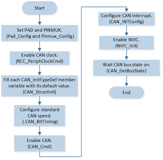
CAN Init Flow
The codes below demonstrate the CAN initialization flow.
void can_board_init(void)
{
   /* Config pinmux and pad for CAN. */
   Pinmux_Config(CAN_TX_PIN, CAN_TX);
   Pinmux_Config(CAN_RX_PIN, CAN_RX);

   Pad_Config(CAN_TX_PIN, PAD_PINMUX_MODE, PAD_IS_PWRON, PAD_PULL_NONE, PAD_OUT_DISABLE, PAD_OUT_LOW);
   Pad_Config(CAN_RX_PIN, PAD_PINMUX_MODE, PAD_IS_PWRON, PAD_PULL_NONE, PAD_OUT_DISABLE, PAD_OUT_LOW);
}

void can_driver_init(void)
{
   CAN_DeInit(CAN0);

   /* Enable rcc for CAN before initialize. */
   RCC_PeriphClockCmd(APBPeriph_CAN0, APBPeriph_CAN0_CLOCK, ENABLE);

   IO_PRINT_INFO1("can_driver_init: BUS state: %d, waiting...", CAN_GetBusState(CAN0));

   /* Initialize CAN. */
   CAN_InitTypeDef init_struct = {0};
   CAN_StructInit(&init_struct);
   init_struct.CAN_AutoReTxEn = DISABLE;

   /* Standard CAN speed = 40mhz / ((brp + 1)*(1 + tseg1 + 1 + tseg2 + 1)) */
   /* Here config to 500khz. */
   init_struct.CAN_BitTiming.b.can_brp = 3;
   init_struct.CAN_BitTiming.b.can_sjw = 3;
   init_struct.CAN_BitTiming.b.can_tseg1 = 13;
   init_struct.CAN_BitTiming.b.can_tseg2 = 4;

   RamVectorTableUpdate(CAN_VECTORn, (IRQ_Fun)can_trx_handler);

   CAN_Init(CAN0, &init_struct);

   /* CAN enable */
   CAN_Cmd(CAN0, ENABLE);

   /* CAN interrupts enable */
   CAN_INTConfig(CAN0, (CAN_BUS_OFF_INT | CAN_ERROR_INT |
                        CAN_RX_INT | CAN_TX_INT), ENABLE);

   /* NVIC enable */
   NVIC_InitTypeDef NVIC_InitStruct;
   NVIC_InitStruct.NVIC_IRQChannel = CAN_IRQn;
   NVIC_InitStruct.NVIC_IRQChannelPriority = 3;
   NVIC_InitStruct.NVIC_IRQChannelCmd = ENABLE;
   NVIC_Init(&NVIC_InitStruct);

   /* polling CAN bus on status */
   while (CAN_GetBusState(CAN0) != CAN_BUS_STATE_ON)
   {
      __asm volatile
      (
            "nop    \n"
      );
   }

   IO_PRINT_INFO1("can_driver_init: BUS ON %d", CAN_GetBusState(CAN0));
}
TX and RX Flow
The CAN module has 16 message buffers for transmitting or receiving frames, corresponding to IDs from 0 to 15. The smaller the message buffer ID, the higher the transmit (TX) priority. The larger the message buffer ID, the higher the receive (RX) priority.
CAN TX flow is shown in the following figure.
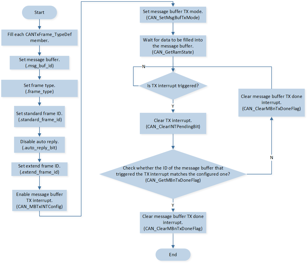
CAN TX Flow
The codes below demonstrate the CAN TX flow.
void can_basic_tx(uint32_t buf_id, CANDataFrameSel_TypeDef frame_type, \
                        uint16_t frame_id, uint32_t ext_id, uint8_t *tx_data, uint8_t data_len)
{
   /* Set CAN Tx message buffer. */
   CANError_TypeDef tx_error;

   CANTxFrame_TypeDef tx_frame_type;

   tx_frame_type.msg_buf_id = buf_id;
   tx_frame_type.frame_type = frame_type;
   tx_frame_type.standard_frame_id = frame_id;
   tx_frame_type.auto_reply_bit = DISABLE;
   tx_frame_type.extend_frame_id = 0;

   switch (frame_type)
   {
   case CAN_EXT_DATA_FRAME:
   case CAN_EXT_REMOTE_FRAME:
      tx_frame_type.extend_frame_id = ext_id;
   case CAN_STD_DATA_FRAME:
   case CAN_STD_REMOTE_FRAME:
      break;
   }

   CAN_MBTxINTConfig(CAN0, tx_frame_type.msg_buf_id, ENABLE);
   tx_error = CAN_SetMsgBufTxMode(CAN0, &tx_frame_type, tx_data, data_len);

   while (CAN_GetRamState(CAN0) != CAN_RAM_STATE_IDLE)
   {
      __asm volatile
      (
            "nop    \n"
      );
   }

   if (tx_error != CAN_NO_ERR)
   {
      IO_PRINT_INFO1("can_basic_tx: tx error %d", tx_error);
   }
}

void can_trx_handler(void)
{
   if (SET == CAN_GetINTStatus(CAN0, CAN_TX_INT_FLAG))
   {
      CAN_ClearINTPendingBit(CAN0, CAN_TX_INT_FLAG);

      for (uint8_t index = 0; index < CAN_MESSAGE_BUFFER_MAX_CNT; index++)
      {
            if (SET == CAN_GetMBnTxDoneFlag(CAN0, index))
            {
               IO_PRINT_INFO1("can_trx_handler: MB_%d tx done", index);
               CAN_ClearMBnTxDoneFlag(CAN0, index);

               /* Add user code. */
            }
      }
   }
}
CAN RX flow is shown in the following figure.
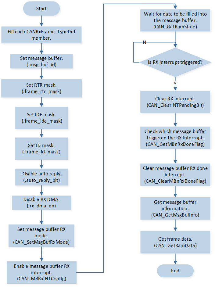
CAN RX Flow
The codes below demonstrate the CAN RX flow.
void can_basic_rx(void)
{
   CANError_TypeDef rx_error;
   CANRxFrame_TypeDef rx_frame_type;
   rx_frame_type.msg_buf_id = 7;

   /* Set 0 to filter related bit, and set 1 to mask related filter. */
   rx_frame_type.extend_frame_id = 0;
   rx_frame_type.standard_frame_id = 0;
   rx_frame_type.frame_rtr_mask = CAN_RX_FRAME_MASK_RTR;
   rx_frame_type.frame_ide_mask = CAN_RX_FRAME_MASK_IDE;
   rx_frame_type.frame_id_mask = CAN_RX_FRAME_MASK_ID;
   rx_frame_type.rx_dma_en = RESET;
   rx_frame_type.auto_reply_bit = RESET;
   rx_error = CAN_SetMsgBufRxMode(CAN0, &rx_frame_type);

   CAN_MBRxINTConfig(CAN0, rx_frame_type.msg_buf_id, ENABLE);

   while (CAN_GetRamState(CAN0) != CAN_RAM_STATE_IDLE)
   {
      __asm volatile
      (
            "nop    \n"
      );
   }

   if (rx_error != CAN_NO_ERR)
   {
      IO_PRINT_INFO1("can_basic_rx: rx error %d", rx_error);
   }

   IO_PRINT_INFO0("can_basic_rx: waiting for rx...");
}

void can_trx_handler(void)
{
   if (SET == CAN_GetINTStatus(CAN0, CAN_RX_INT_FLAG))
   {
      CAN_ClearINTPendingBit(CAN0, CAN_RX_INT_FLAG);

      for (uint8_t index = 0; index < CAN_MESSAGE_BUFFER_MAX_CNT; index++)
      {
            if (SET == CAN_GetMBnRxDoneFlag(CAN0, index))
            {
               IO_PRINT_INFO1("can_trx_handler: MB_%d rx done", index);
               CAN_ClearMBnRxDoneFlag(CAN0, index);
               {
                  CANMsgBufInfo_TypeDef mb_info;
                  CAN_GetMsgBufInfo(CAN0, index, &mb_info);

                  uint8_t rx_data[8];
                  memset(rx_data, 0, 8);
                  CAN_GetRamData(CAN0, mb_info.data_length, rx_data);

                  CANDataFrameSel_TypeDef frame_type = CAN_CheckFrameType(mb_info.rtr_bit, mb_info.ide_bit,
                                                                           mb_info.edl_bit);

                  IO_PRINT_INFO3("[can_trx_handler: frame_type %d, frame_id = 0x%03x, ext_frame_id = 0x%05x", \
                                 frame_type, mb_info.standard_frame_id, mb_info.extend_frame_id);

                  for (uint8_t index = 0; index < mb_info.data_length; index++)
                  {
                        IO_PRINT_INFO2("can_trx_handler: rx_data [%d] 0x%02x", index, rx_data[index]);
                  }

                  /* Start rx next time. */
                  can_basic_rx();
               }
            }
      }
   }
}
FIFO Mode
The highest four message buffer will be used as FIFO memory when FIFO function is enabled. The RX FIFO uses the configuration of the message buffer with ID 12 to do filtering (ID and mask) and read out. RX interrupt is also generate with the message buffer with ID 12. The FIFO has the highest RX priority.
CAN FIFO flow is shown in the following figure.
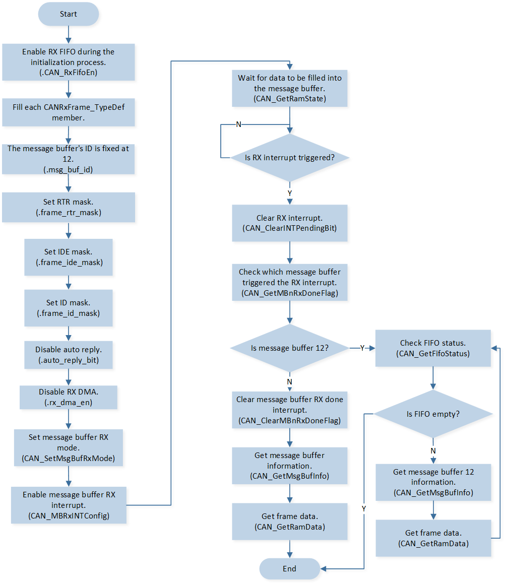
CAN FIFO Flow
The codes below demonstrate the CAN FIFO mode.
void can_basic_rx(void)
{
   CANError_TypeDef rx_error;
   CANRxFrame_TypeDef rx_frame_type;
   rx_frame_type.msg_buf_id = CAN_MESSAGE_FIFO_START_ID;

   /* Set 0 to filter related bit, and set 1 to mask related filter. */
   rx_frame_type.extend_frame_id = 0;
   rx_frame_type.standard_frame_id = 0;
   rx_frame_type.frame_rtr_mask = CAN_RX_FRAME_MASK_RTR;
   rx_frame_type.frame_ide_mask = CAN_RX_FRAME_MASK_IDE;
   rx_frame_type.frame_id_mask = CAN_RX_FRAME_MASK_ID;
   rx_frame_type.rx_dma_en = RESET;
   rx_frame_type.auto_reply_bit = RESET;
   rx_error = CAN_SetMsgBufRxMode(CAN0, &rx_frame_type);

   CAN_MBRxINTConfig(CAN0, rx_frame_type.msg_buf_id, ENABLE);

   while (CAN_GetRamState(CAN0) != CAN_RAM_STATE_IDLE)
   {
      __asm volatile
      (
            "nop    \n"
      );
   }

   if (rx_error != CAN_NO_ERR)
   {
      IO_PRINT_INFO1("can_basic_rx: rx error %d", rx_error);
   }

   IO_PRINT_INFO0("can_basic_rx: waiting for rx...");
}

void can_trx_handler(void)
{
   if (SET == CAN_GetINTStatus(CAN0, CAN_RX_INT_FLAG))
   {
      CAN_ClearINTPendingBit(CAN0, CAN_RX_INT_FLAG);

      for (uint8_t index = 0; index < CAN_MESSAGE_BUFFER_MAX_CNT; index++)
      {
            if (SET == CAN_GetMBnRxDoneFlag(CAN0, index))
            {
               IO_PRINT_INFO1("can_trx_handler: MB_%d rx done", index);
               CAN_ClearMBnRxDoneFlag(CAN0, index);

               if (index == CAN_MESSAGE_FIFO_START_ID)
               {
                  CANFifoStatus_TypeDef fifo_status;
                  CAN_GetFifoStatus(CAN0, &fifo_status);

                  while (fifo_status.fifo_msg_empty == RESET)
                  {
                        CANMsgBufInfo_TypeDef mb_info;
                        CAN_GetMsgBufInfo(CAN0, index, &mb_info);

                        uint8_t rx_data[8];
                        memset(rx_data, 0, 8);
                        CAN_GetRamData(CAN0, mb_info.data_length, rx_data);

                        CANDataFrameSel_TypeDef frame_type = CAN_CheckFrameType(mb_info.rtr_bit, mb_info.ide_bit,
                                                                              mb_info.edl_bit);

                        IO_PRINT_INFO3("can_trx_handler: frame_type %d, frame_id = 0x%x, ext_frame_id = 0x%x", \
                                       frame_type, mb_info.standard_frame_id, mb_info.extend_frame_id);

                        for (uint8_t index = 0; index < mb_info.data_length; index++)
                        {
                           IO_PRINT_INFO2("can_trx_handler: rx_fifo_data [%d] 0x%02X", index, rx_data[index]);
                        }

                        CAN_GetFifoStatus(CAN0, &fifo_status);
                  }

                  /* Start rx next time. */
                  can_basic_rx();
               }
               else
               {
                  CANMsgBufInfo_TypeDef mb_info;
                  CAN_GetMsgBufInfo(CAN0, index, &mb_info);

                  uint8_t rx_data[8];
                  memset(rx_data, 0, 8);
                  CAN_GetRamData(CAN0, mb_info.data_length, rx_data);

                  CANDataFrameSel_TypeDef frame_type = CAN_CheckFrameType(mb_info.rtr_bit, mb_info.ide_bit,
                                                                           mb_info.edl_bit);

                  IO_PRINT_INFO3("[can_trx_handler: frame_type %d, frame_id = 0x%03x, ext_frame_id = 0x%05x", \
                                 frame_type, mb_info.standard_frame_id, mb_info.extend_frame_id);

                  for (uint8_t index = 0; index < mb_info.data_length; index++)
                  {
                        IO_PRINT_INFO2("can_trx_handler: rx_data [%d] 0x%02x", index, rx_data[index]);
                  }

                  /* Start rx next time. */
                  can_basic_rx();
               }
            }
      }
   }
}
Note
When a message buffer has finished sending or receiving data, it must be reconfigured before it can send or receive data again.
Auto Reply Function
When the CAN’s auto reply function is enabled, the CAN can automatically reply upon receiving a remote frame or automatically receive upon completing the transmission of a remote frame.
When the CAN needs to automatically reply upon receiving a remote frame, the message buffer should be set to TX mode. Refer to the code below:
void can_receive_remote_auto_tx_reply(void)
{
   CANError_TypeDef tx_error;
   CANTxFrame_TypeDef tx_frame_type;

   uint8_t tx_data[8];
   for (uint8_t index = 0; index < 8; index++)
   {
      tx_data[index] = index;
   }

   tx_frame_type.msg_buf_id = 0;
   tx_frame_type.frame_type = CAN_STD_DATA_FRAME;
   tx_frame_type.standard_frame_id = 0x01;
   tx_frame_type.extend_frame_id = 0x01;
   tx_frame_type.auto_reply_bit = SET;
   CAN_MBTxINTConfig(CAN0, tx_frame_type.msg_buf_id, ENABLE);
   tx_error = CAN_SetMsgBufTxMode(CAN0, &tx_frame_type, tx_data, 8);

   while (CAN_GetRamState(CAN0) != CAN_RAM_STATE_IDLE)
   {
      __asm volatile
      (
            "nop    \n"
      );
   }

   if (tx_error != CAN_NO_ERR)
   {
      IO_PRINT_INFO1("can_receive_remote_auto_tx_reply: tx error %d", tx_error);
   }

   IO_PRINT_INFO1("can_receive_remote_auto_tx_reply: tx auto reply remote frame id: 0x%x",
                  tx_frame_type.standard_frame_id);
}
When the CAN needs to automatically receive after sending a remote frame, the message buffer should be set to RX mode. Refer to the code below:
void can_send_remote_auto_receive_reply(void)
{
   CANError_TypeDef rx_error;
   CANRxFrame_TypeDef rx_frame_type;

   rx_frame_type.msg_buf_id = 10;
   rx_frame_type.extend_frame_id = 0;
   rx_frame_type.standard_frame_id = 0x10;
   rx_frame_type.frame_ide_bit = CAN_IDE_STANDARD_FORMAT;
   rx_frame_type.frame_rtr_bit = CAN_RTR_DATA_FRAME;
   rx_frame_type.frame_rtr_mask = CAN_RX_FRAME_UNMASK_RTR;
   rx_frame_type.frame_ide_mask = CAN_RX_FRAME_UNMASK_IDE;
   rx_frame_type.frame_id_mask = 0;
   rx_frame_type.rx_dma_en = RESET;
   rx_frame_type.auto_reply_bit = SET;
   rx_error = CAN_SetMsgBufRxMode(CAN0, &rx_frame_type);

   CAN_MBRxINTConfig(CAN0, rx_frame_type.msg_buf_id, ENABLE);

   while (CAN_GetRamState(CAN0) != CAN_RAM_STATE_IDLE)
   {
      __asm volatile
      (
            "nop    \n"
      );
   }

   if (rx_error != CAN_NO_ERR)
   {
      IO_PRINT_INFO1("can_send_remote_auto_receive_reply: rx error %d", rx_error);
   }

   IO_PRINT_INFO1("can_send_remote_auto_receive_reply: rx auto receive data frame id: 0x%x",
                  rx_frame_type.standard_frame_id);
}
GDMA Mode
CAN supports only 32bit aligned transfer, so the data size for GDMA must be set to word.
GDMA_InitStruct.GDMA_SourceDataSize      = GDMA_DataSize_Word;
GDMA_InitStruct.GDMA_DestinationDataSize = GDMA_DataSize_Word;
TX GDMA uses memory to memory mode. In this mode, GDMA will not need any handshake with CAN. A frame has been prepared in RAM ready to transmit, GDMA is used to move the message to the CAN register interface.
CAN TX GDMA flow is shown in the following figure.
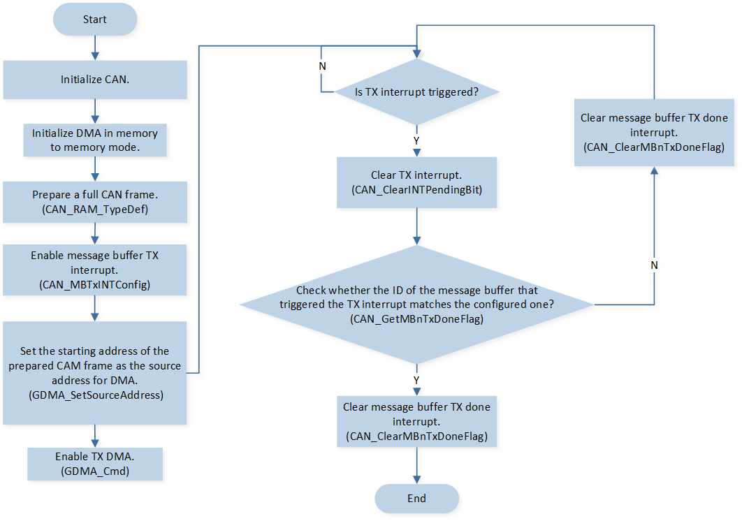
CAN TX GDMA Flow
When using the RX GDMA function, the transfer is initiated by GDMA, and some transfer parameters are set by the CPU depending on CAN. When one CAN message is successfully received, if the message buffer is set up with the RX GDMA function, it will generate an interrupt to the CPU. Then the CPU fills in the GDMA source address and data length. Then GDMA will start to read the received CAN message from CAN. After all messages have been read from the register by GDMA, the GDMA will generate a signal to inform CAN that the GDMA transfer has been finished. The RX GDMA message buffer priority is the same as the RX message buffer.
CAN RX GDMA flow is shown in the following figure.
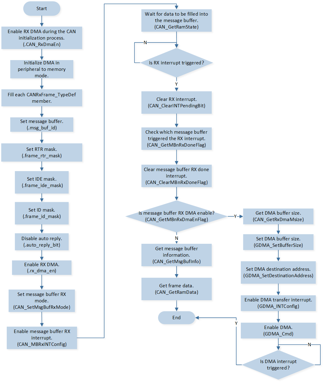
CAN RX GDMA Flow
For details, please refer to src\sample\io_demo\canbus\trx_dma\can_trx_dma.c.